
 De
De  Es
Es  Fr
Fr 

nanoCAD Tips & Tricks for Plotting
All the plotting-related functionality of nanoCAD is found in the Plot group on the Output ribbon (Fig. 1).
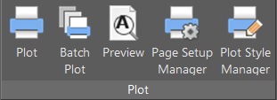
Fig. 1: Plot group, Output ribbon
There aren't as many commands here as in the blocks section, but there are far more settings. Below we've provided a number of tips to bring some clarity to the settings and help you automate your plotting.
Tip 1: Page Setup Manager
Let’s say, you suddenly need to plot a number of pages with the same setup: plotter, page format, page orientation, plot area, etc. Having to enter the dialog window and set up the same page over and over again is time-consuming. The nanoCAD solution is the Page Setup Manager. All you have to do to set everything up quickly is:- open the Page Setup Manager (Fig. 2)
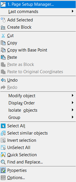
Fig. 2: Opening the Page Setup Manager
- Press New (Fig. 3)
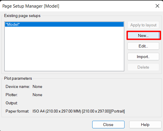
Fig. 3: Operating the Page Setup Manager
- enter a unique plot setup name (Fig. 4)

Fig. 4: New plot set
- Press the OK button. When the Page Setup dialog box opens, enter all the necessary settings for the current and subsequent pages, as shown in the example of Fig. 5.
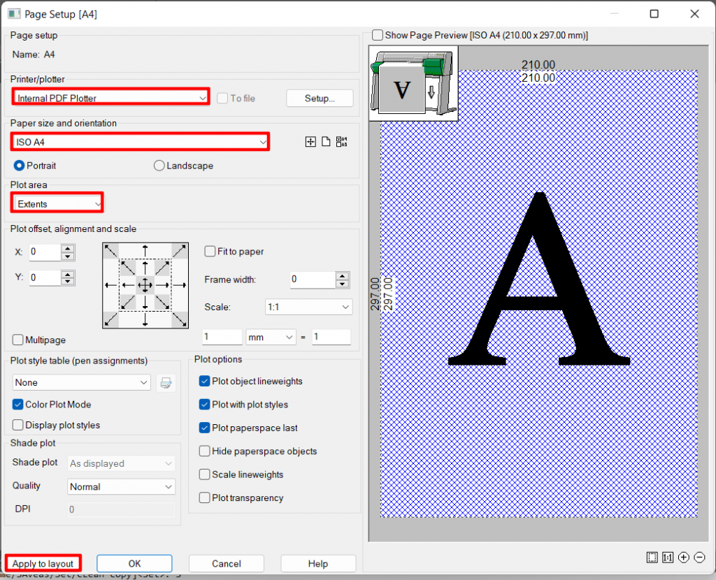
Figure 5: Page Setup
- apply the settings to the layout by pressing the corresponding button in the bottom left corner of the dialog window (see Fig. 5).
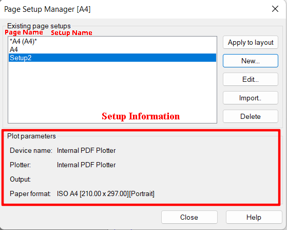
Figure 6: Result after the page setup is configured
In the Page Setup Manager, we can see the Page Name with the settings assigned (indicated in parentheses) - Fig 6. A single document can contain any quantity of setup configurations. Brief accompanying information is presented in the bottom of the window to avoid any confusion for the user.
To use the obtained setup in other pages, go to the Page Setup Manager (Fig. 7), highlight the relevant setup, and click Apply to layout.
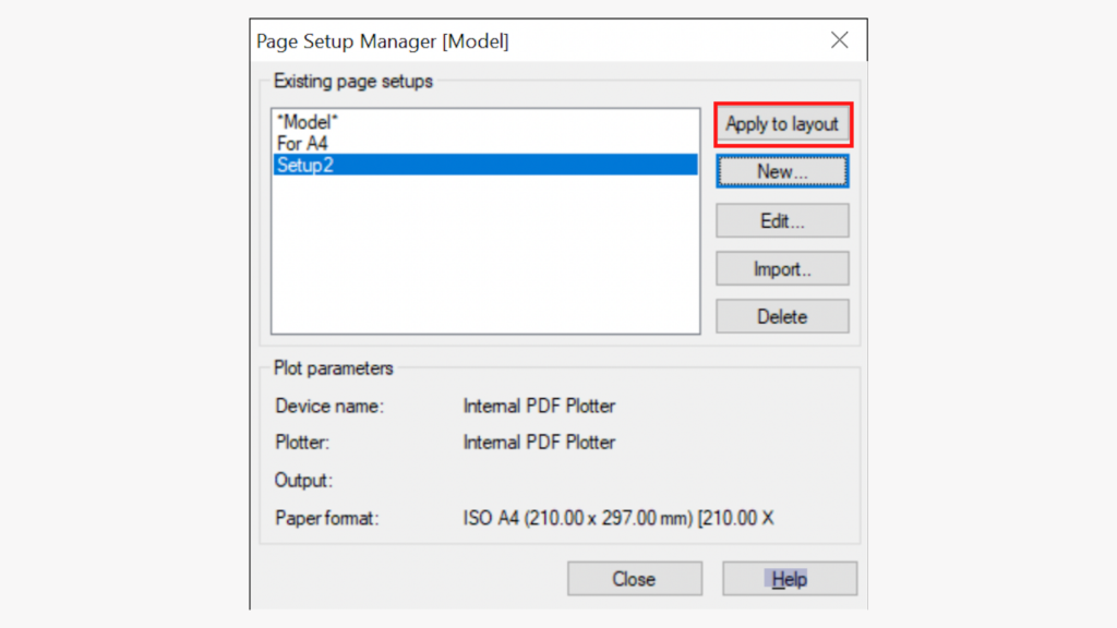
Figure 7: Executing the Apply to Layout command
Applying the setup is handy when plotting two or more pages with the same configuration parameters.
Tip 2: Batch Plotting
If the page setup presented in the previous section still seems too long, you can turn to batch plotting instead (Fig. 8). The PUBLISH command opens the corresponding window.
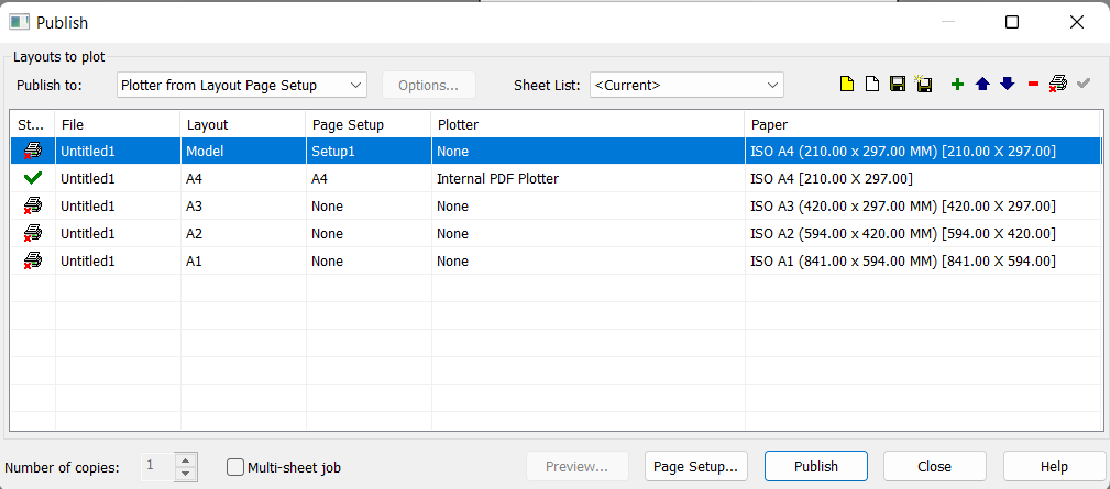
Fig. 8. Batch Plot dialog window
You can use this tool to:
- plot pages of several documents open in the program
-
configure page lists independently and set their plotting output order:

- save page lists (.plst) and transfer them: Data% \Nanosoft\nanoCAD x64 XX\PlotConfigs
-
set up the same plotting device for all pages. If any individual page was not assigned with a plot set, you will see a Plotting Complete (
 ) label across from those page names () in the Batch Plot window and they won't be plotted. To plot all the pages on the same device without additional settings, choose the plotter of your interest across the Publish to line on the drop-down menu list. The pages will switch from the status () to Plot Page status (
 ).
).
Tip 3 Preview
Few people are aware of this, but there is a preview option in nanoCAD. It appears as a new window separate from the Plot dialog and works faster. Plus, you can activate the plotting with just two clicks from the preview window. Open the preview window by pressing Ctrl+F2 or the Plot PREVIEW command. Note that it works only if a specific plotter is selected for the page.Tip 4: Document Counter
If you work with internal plotters (PDF, EMF, DWF, DWFx), you are familiar with the save document dialog window and the frequent notifications about multiple documents with the same name. Let’s create a counter to solve these problems.- Call the PAGESETUP command (Page Setup Manager)
- Create an unnamed plot set
- Choose the Internal PDFPlotter in the Page Setup dialog window (Fig. 9)
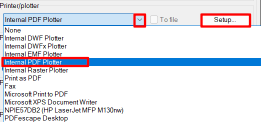
Figure 9 Choosing the default PDF plotter
- Click Setup
- Change the following settings in the Internal PDF Plotter window (Fig. 10):
- Set up the Use Predefined File Name section.
- In the If file exist field, select Auto-numbering file name
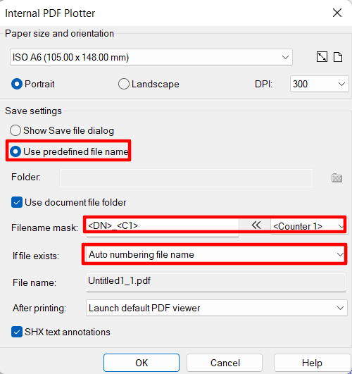
Fig: 10 Internal PDF Plotter setup
As a result of plotting three files, for example, we will get the names without windows popping up.
Tip 5: Editing the Paper Size and Orientation List
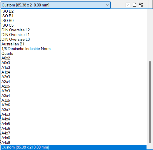
Fig. 11: Paper Size and Orientation list before editing
If you usually use the most common formats, since looking for any other format takes a long time (Fig. 11), don’t worry, the paper formats filter in nanoCAD will solve the issue in a couple of clicks.
Press the Filter paper button
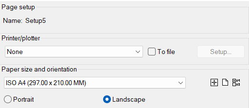
Fig. 12: Page setup dialog window
The Edit paper list dialog window will appear (Fig. 13).
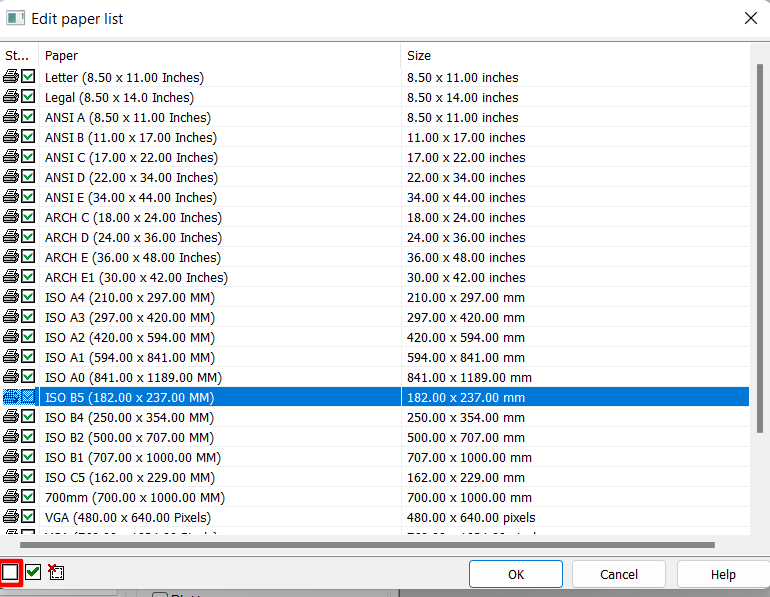
Fig 13: Paper Format List Editor dialog window
Disable the formats you don’t need by pressing the Turn off paper button (
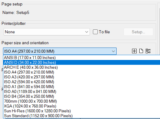
Fig. 14: The Paper Size and Orientation List after editing
The nanoCAD search is more convenient than ever. In the Page Setup window, you can also add the user paper format by pressing the Add custom paper size button (
Tip 6: Plot Style
It’s kind of an old but still handy function.There are two types of plot styles: named (.stb) and color-dependent (.ctb).
The objective of the color-dependent plot style is to adjust the properties of specific color lines on a draft: type, intensity, weight, color, and more. Let’s take a look at the example.
- We sketch random shapes with different colors (Fig. 15).
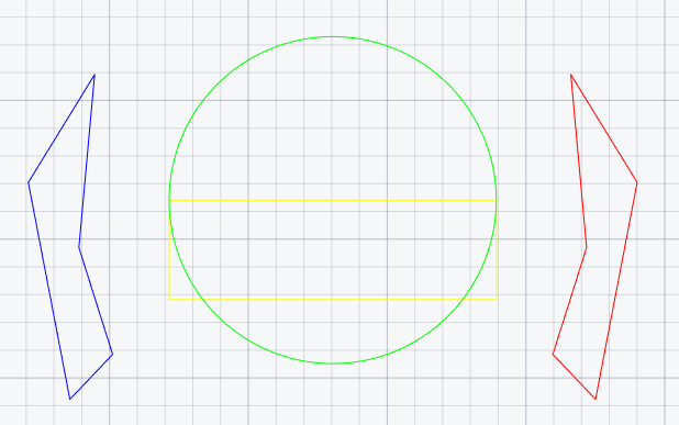
Fig. 15: Shape types before plot styles are applied
- Call the PLOT command.
- Set a flag across from color-dependent mode and choose New from the drop-down list (Fig. 16).
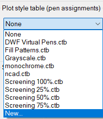
Fig. 16: Creating a new color-dependent plot style
- In the dialog window that pops up, enter the name with the ctb extension and press OK (Fig. 17).
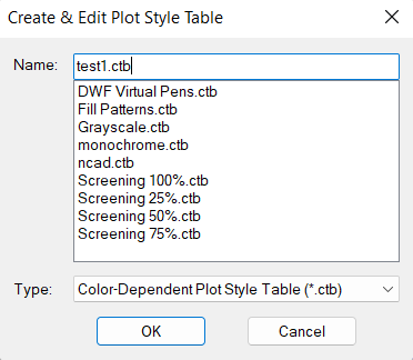
Fig. 17: Entering the plot style name
- In the Plot Style Table Editor, change the object properties as shown in Fig. 18.
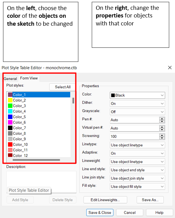
Fig. 18: Changing object properties
The result of the changes is shown in Fig. 19.
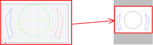
Fig. 19: The appearance of the shapes after the color-dependent plot style is applied
As we can see, the plot styles settings did not affect the draft objects in any way. We changed only the properties of the objects in the plot draft output.
The objective of the named plotting style is to change the object properties on a specific layer.
Let’s complete the same sequence of actions as we did in the color-dependent mode, but this time remove the flag across from color-dependent mode and write Name.stb in the name. Change the necessary settings in the Form View tab and press Save & Close in the Plot Style Table Editor.
Go to the Layers (LAYER command) and choose the layer you want to apply the settings to (all objects on the layer 0).
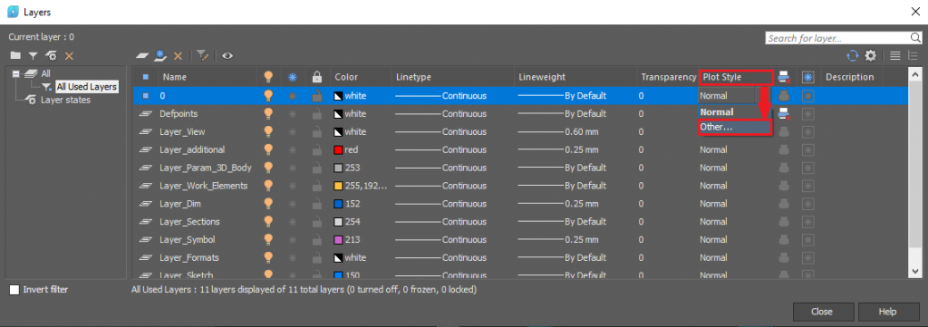
Fig. 20: Layers dialog window
On the layer 0, choose Other from the Plotting Style drop-down menu (Fig. 20).
In the dialog window that pops up, choose the plot style file and the corresponding setting (Fig. 21). Click OK.
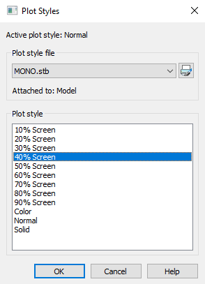
Fig. 21: Choosing the configured plot style
See the result in Fig. 22.
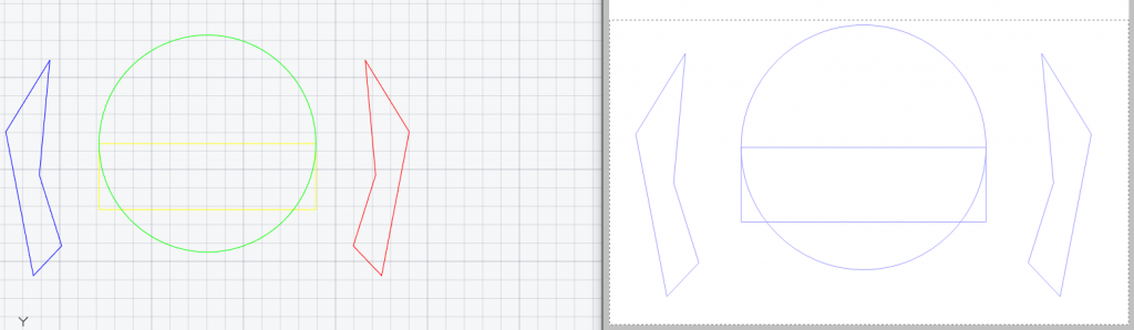
Fig. 22: Before (left) and after (right) applying the named plot style
Today we've looked at some of the most interesting and handy dwg-file plot settings.
Good luck with your designs.