nanoCAD 25 Features
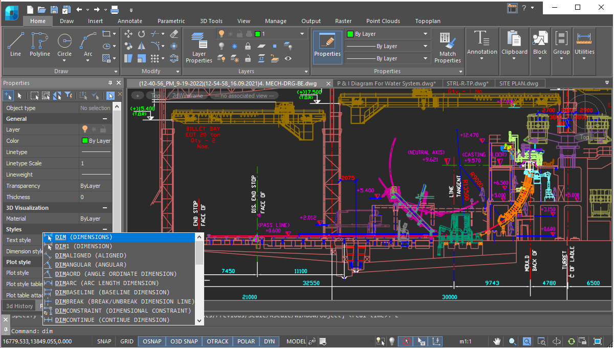
User Interface
nanoCAD’s operating principles are designed to look and feel just like other well-known CAD systems. This means that any experienced designer can master nanoCAD instantly. Drawing spaces, command lines, positions of menu items, and icons are recognizable, so there is nearly no need for retraining. You can switch back and forth between the modern ribbon and classic CAD user interfaces instantly. nanoCAD’s visual interface editor customizes almost every aspect of nanoCAD. Settings can be copied from one workstation to another.
Direct DWG Format Support
The wide range of DWG versions supported by nanoCAD (from DWG R11 to today’s DWG 2018) means that drawings can be saved and reused without conversion or data loss in nanoCAD and other CAD systems. To provide a unified processing process, nanoCAD is one of the few systems on the CAD market to offer full support for DWG and all aspects related to it.

Saving unsaved files
nanoCAD’s new save feature prevents data loss in cases where the Save option is accidentally declined, such as when many files are closed at the same time. Other scenarios include deleting objects and then saving the drawing, or when the undo/redo mechanism is turned off. In these cases, the new Save File History option restores files from a temporary storage.

Open API
nanoCAD offers an extensive application programming interface (API) for developing third-party applications and add-ons. The well-built architecture of our API allows you to create applications of any complexity. To write utilities and small applications quickly, developers can use the built-in Script Editor with scripts based on ActiveX Automation (JS, VBS, and so on), as well as for LISP with DCL dialog control language.
For more complex and feature-rich add-ons, nanoCAD supports .NET and C ++. The nanoCAD Developer Club supports members and provides with access to the following APIs:
Access to the NanoCAD Developer Club is open after registering on the community site. Welcome to the world of programming for nanoCAD!
For more complex and feature-rich add-ons, nanoCAD supports .NET and C ++. The nanoCAD Developer Club supports members and provides with access to the following APIs:
- .NET API – a modern API for developing .NET applications
- NRX – the classic C ++ API for creating and migrating applications in C ++
- MultiCAD API - a unique C++ API for writing cross-platform CAD applications
- MultiCAD.NET API -- (currently in alpha) a cross-platform .NET API for creating custom primitives on .NET
Access to the NanoCAD Developer Club is open after registering on the community site. Welcome to the world of programming for nanoCAD!
.png)
Dynamic input
Dynamic input helps you set dimensions and sizes of drawing elements, without needing to access the command line. It’s heads-up drafting with pointer input, dimension input, and dynamic prompts. Dynamic input is available for creating and editing objects, which greatly simplifies working with drawings.
.png)
IFC support
nanoCAD can import IFC files into a DWG document. It is possible to perform numerous operations on imported BIM objects, such as to compile reports on models created in BIM-systems. Add to this an updated tools for 3D navigation in parallel and perspective projection, adaptive zoom, camera and observer head rotation, accelerated performance in saturated 3D models - and you will get a universal IFC-viewer based on DWG and BIM-models.
.png)
Tool palettes
Tool palettes give you fast, easy access to your most-used commands and blocks. Organizations can define their own sets of standard blocks, hatches, and scripts and then load them on all workstations to access them with a single click.
.png)
Drawing Comparison
nanoCAD allows you to find differences between two similar-looking drawings in model space. It detects objects that have been modified, added, or removed from drawings being compared.
.png)
Powerful Excel-style table editor
nanoCAD’s table editor blows away the competition with its powerful set of database-like capabilities, along with tables that embed macros and formulas in cells.
.png)
2D/3D Point Clouds
nanoCAD imports point clouds into drawings from laser scanners like TerraSolid (bin), ASPRS (las), and Leica (ptx and pts), as well as generic point cloud files (pcd). The Import dialog box is powerful enough to import only the regions of clouds you need. You can create and modify clouds with sections and clips, and tune visualization parameters, such as color by elevation.
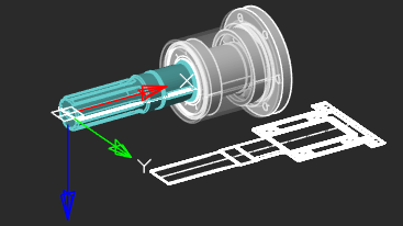
Extensive Commands for Creating and Editing 2D/3D Objects
nanoCAD contains all tools necessary for design:
- Create and edit 2D and 3D objects, text, and design elements
- Adjust display settings and printing for technical documentation
- Create and use any kind of table and specifications, based on block attributes
- Set up working environments according to international standards
- View, create, and edit 3D surface objects
- Effectively share technical information and drawings with designers working in other CAD systems
- Place raster images (scanned drawings, text, tables, photographs) in designs
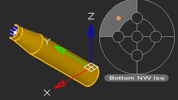
Locator Function
With the Locator tool, you interactively rotate the view of a model while holding down the Alt key, and then select any point on the locator circle, or choose one of the four marked points to rotate a view by 90◦.The arrow points to the new view rotation position.
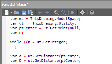
Scripting Engine
nanoCAD’s scripting engine allows everyday users to automate routine tasks. You can write macros using Visual Basic Script, Java Script, and other scripting languages supported by Microsoft Windows as well as use the built-in LISP interpreter.
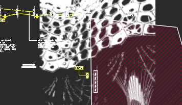
Transparency Command
The new Transparency command toggles the transparency of background pixels in raster images. Access this new command through the ribbon’s Visualization group, the Raster menu, or the Raster toolbar.
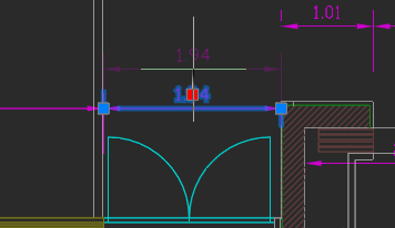
Associative Design Elements
For associative dimensions and multileaders created in other CAD systems, associativity with objects is maintained in nanoCAD. Associative links with dimensions can be broken by shifting the grips of extension lines.
More great features
Batch Plot Tools
nanoCAD lets you set up multiple plot areas and plot multi-page sets, which is useful for printing large drawings on small-format printers. The Batch Plot command creates and prints drawing sets without requiring you to babysit the printing process.
Enhanced UNDO/REDO
nanoCAD now moves forwards and backwards through isolated and unisolated objects, affecting the standard Undo/Redo mechanism.
Classifying points and establishing named views
An extensive toolkit and parameters are available for the automatic classification of terrain and other categories based on specified criteria.
NEW
Enhanced External References
nanoCAD improves the External References panel so that external references can be loaded and unloaded, be bound to the current drawing, and to report updates made to xref’ed files – all without needing to reload the current drawing. The redesigned panel also completely removes external references that had been inserted in the current drawing, along with all their associated data.
Enhanced Groups
nanoCAD’s object grouping tool has been reworked. Its functions are added to the context menu (right-click in the drawing), shown as individual commands in the ribbon’s Group section (found in the Main tab), and to the Group toolbar.
Relocating Base Points of Blocks
nanoCAD can change the position of base points in block definitions. The base point corresponds to the location of grips at the insertion points of block references.
New ways to create and modify geometric objects
nanoCAD now draws arcs (including elliptical ones) in the direction that the cursor moves. Circles can be drawn tangent to three other objects. Ellipses and closed polylines can be broken by picking two points. Open objects can be lengthened in both directions. Spline fit points can now be edited by holding down the Ctrl key.
Registering point clouds by reference points with error control
Mutual orientation of multiple point clouds enables registration to identify transformation parameters for any number of reference point groups. Two techniques are employed: pairwise and iterative.


 De
De  Es
Es  Fr
Fr  Pt
Pt 
