Construction Features
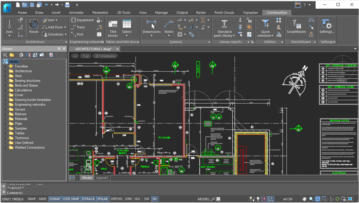
Smart drawing elements
The Construction module includes a massive number of smart drawing elements to automate routine operations like layout generation, sectioning, and detailing of buildings.
- Database of parametric elements
- Technical specifications editor
- Breaks for hiding underlying geometry
- Designation of permanent joints
- Ground borders
- Level marks
- View and section designations
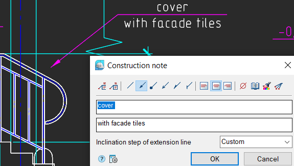
- Notes
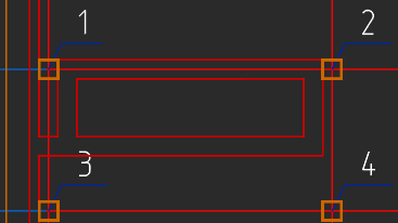
Smart drawing and editing utilities
The Construction module turns entities that look like tables (lines and text) into table objects. It offers utilities for automatically numbering drawing objects, increasing and decreasing selected areas, and creating custom objects with parametric properties.
- Define custom hatch patterns in *.pat files
- Draw fully customized arrays of objects
- Create and calculate plate arrays
- Design hole charts
- Perform advanced calculations using the built-in calculator
- Carry out static beam calculations
- Calculate geometric properties of user-defined sections
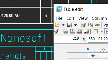
Powerful table editor
The Construction module features a very powerful built-in table editor that generates tables of any complexity. Users can convert tables imported from other CAD programs to nanoCAD’s own format. As well, it recognizes tables made from primitives. Tables offer the following functions:
- In-place editing of tables
- Pencil sketching in cells
- Cell styles that specify text styles, alignments, line weights, value rounding
- Table headers and footers
- Calculations between cells
- Direct interaction with Clipboard, Excel, and Open Office
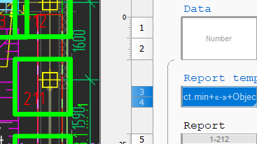
Automatic reports
The Construction module creates reports from lists, specifications, and object data in drawings. Reports access data extracted from objects, architectural components, design elements, blocks with attributes, and the Construction module’s library of parts. There is no need to worry that reports might be not up to date.
- Generate analyses directly from rooms in drawings
- Automatically update reports as properties of objects change
- Save reports as templates for use in other drawings to generate the same kinds of reports and analyses
- Functions are available to all users, with no programming needed
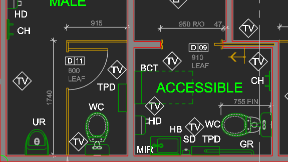
Architectural layouts
The Construction module lays out building plans using discipline-specific tools and objects:
- Straight and arc-shaped walls that join automatically
- Custom templates for walls that define geometry, attributes, and multi-layer (ply) construction properties
- Walls edited with trim, break, and join commands, or by using grips
- Insertion of windows and doors using the built-in database of components
- Lay out rooms and spaces on plans, with customized space attributes and composition
- Automatic calculation and creation of room analyses and lists of compositions
- Insertion of interior elements using a database of templates
- Generating 3D models and IFC-format documentation with the Project Manager
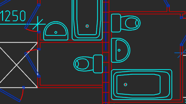
Engineering networks
The Construction module includes a set of tools for engineering networks, such as internal communications, HVAC, and gas supplies, with templates for traces, equipment, and connectors.
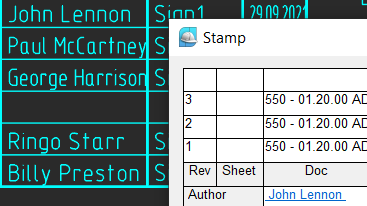
Parametric borders and title blocks
The Construction module provides drawing borders and title blocks that are parametric. This save you time when completing drawings:
In addition to the collection of pre-made drawing borders and title blocks, you can create your own parametric borders and stamps using the Format and Stamp Wizard.
- Multi-view drawing borders use dedicated grips and switches to change their size, format, and orientation
- Special grips change aspects of title blocks
- Stamps dialog box fills in reusable text in title blocks
In addition to the collection of pre-made drawing borders and title blocks, you can create your own parametric borders and stamps using the Format and Stamp Wizard.
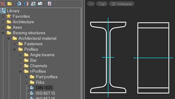
Parametric parts library
The Construction Module comes with a built-in library that contains a vast number of parametric parts and templates. Each parametric object has its own set of size tables, display modes, and behaviors. As it is an open database, parametric objects can be edited with the MechWizard tool.
The parametric parts library contains the following components:
The parametric parts library contains the following components:
- Wall, window, door templates
- Concrete foundations, beams, columns
- Steel profiles in ISO, IS, DIN, GOST standards
- Fasteners in ISO, DIN, IS, CSN, PN/M, GOST standards
- Drawing borders, title blocks
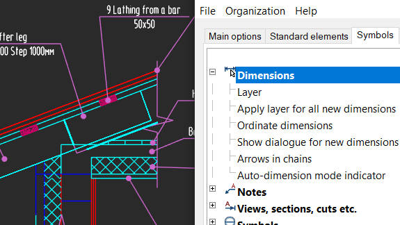
Customized settings
The Construction module takes a flexible approach to object settings. All pre-configured elements provided the module can be redefined using the object settings window, as required by design firms, and then copied to all workstations.
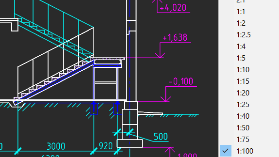
Objects scaling
The Construction module supports drawings with many views at different scales. With just two clicks, you can adjust the scale of drawings, both for specific objects and for entire drawings. The symbol scale adjusts the sizes of text, dimensions, and linetypes automatically in model space and in layouts using viewports.
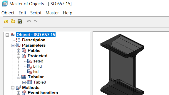
Create custom parametric objects
Parametric objects are an improvement over dynamic blocks as they contain not just grips for changing blocks, but also offer dialog boxes with choices of options. The Master of Objects allows you to edit library items and create parametric objects to your needs.
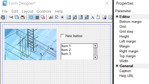
Create custom dialog boxes
It can be easier to manipulate objects with dialog boxes. The Form designer allows you to create dialog boxes for leaders, blocks, nanoCAD tables, and custom objects. Auxiliary variables for objects can be entered into a form, and arranged in an order convenient to you.
Parametric design elements
The Construction module employs objects that follow preset rules based on design requirements of building projects. All drawing elements that make up AEC objects (such as notches, lines, and text) contain parameters that control their display and geometric configurations.
Object grips
The Construction Module’s smart objects interact with other objects during editing. Grips stretch, rotate, move, and rotate objects, alter their geometry, and launch object-specific commands. These commands can also be executed through the context menu. Object-specific commands include actions that add extension lines, align text, mirror objects, and change arrowhead styles.


 De
De  Es
Es  Fr
Fr  Pt
Pt 
