
 De
De  Es
Es  Fr
Fr  Pt
Pt 

New in Mechanica
Version 26
2D and 3D versions are available.
Additional parameters can be added to the end of the specification name.
Flange connections to welded pipelines and universal pipes have been implemented. Correct gasket attachment to flanges and mating flanges are now ensured, and the sealing surface of the flanges is aligned. Changes in diameter, pressure, or sealing surface cause the entire flange connection to be rebuilt accordingly.

The objects have 2D and 3D versions.

Corrected 3D pin representations.
Version 25

- the dimension tolerance is not symmetrical
- the upper tolerance is not zero
- the tolerance display method includes the dimension nominal, upper and lower deviations


Version 24
The following properties have been added:
- material category;
- material;
- control group;
- additional parameters.
All these parameters can be selected in accordance with the requirements of the relevant standards. It has become more convenient to create a sign for flanges and flange blanks for specifications.
And in nanoCAD Mechanics 24 a metric radius 3D thread has been added.
Now you can make 3D parts with such threads, both internal and external, in addition, such threads have appeared on base elements.

The format of angular units Deg/Min/Sec has been corrected.
The update of detail views from viewports has been corrected.
3D models of pipeline fittings for connections along the internal cone have been made.
3D models of plugs and stoppers have been made.


The drawing of Tooth wheels has been corrected.
Sheet Solids
The bugs have been fixed, due to which a bend was not created according to a sketch:
- along line with angle inside
- along edge in the sketch plane
- with more than two lines
Construction of sweeps on solids with NURBs-surface has been corrected.
Version 23
The file type can be changed depending on the purpose:
- not specified
- part
- assembly
The file with the assigned type Not selected is a regular *.dwg file, in which you can draw up two-dimensional drawings and specifications.
For files of the Part and Assembly types, the following properties have been added, which are necessary when creating specifications for 3D models:
- section
- name
- designation
- note
In the properties of parts and assemblies files (Stamps Data section), fields for the main, inventory and reference inscriptions of drawings and specifications have been created. When creating a drawing or specification, they are associated with the corresponding format fields.

When using external references in 3D model files of parts and assembly units, the corresponding drawings can be formed in the paper space of external files without overloading the model space and maintaining the associativity of the 3D model and drawing.
In the properties of parts and assembly units, you can specify such data as section, name, designation and note, as well as data for filling drawing stamps. If you use a part or assembly as a block multiple times, copy the block or use the Insert Block command. By assembling from blocks, you can generate a specification and prepare an assembly drawing.

When forming specification from a 3D model, data are collected from the assembly, such as the names and designations of parts and assembly units, sections of the specification in which these assemblies should fall, as well as notes for the specification.

When forming specification from a 3D model, data are collected from the assembly, such as the names and designations of parts and assembly units, sections of the specification in which these assemblies should fall, as well as notes for the specification.

In views of 3D model of an assembly, you can place numbered leaders of specification positions. Specification leaders position numbers are synchronized with the specification editor, and specification elements can be renumbered.


In the Mechanica module, grid display in model space is now disabled by default.
Version 22
When creating a broken section, all database items that fall within its frame are shown in section. In this case, if the database item does not have a section view, its normal view will be displayed.
When using geometry that falls into a local section, it is reshaped by the Refresh view frame button or by mcregenobj command.


For old standards, the following properties have been added:
- Thread direction
- Thread tolerance field
- Material
- Strength class/group
- Type/grade of steel
- Coating
- Coating thickness
For new standards, the following properties have been added:
- Material
- Strength class
- Coating
- Coating element
- Coating thickness
- Finishing of the coating
- Coating method
- Coating lubrication
- Duration of trials
Additional specification templates with the customer's stamp have been made for all specification templates available in the database (simple, group type A and type B, group type A up to 3 versions and plasma). Columns have been added in these templates for the customer sign, decision numbers, approval years, and customer index.


Version 21
Mechanica has transitioned to a new materials database management system that takes into account user wis list items. The new database includes elements from the general database of objects, as well as these improvements over the old one:
-
More complex and varied materials
-
Custom materials
-
Multi-line notes for materials
Mechanica’s Hole fill tool improves the conversion to threaded holes:
-
Hole diameters becomes the outer diameter of the threads
-
Internal thread diameters depend on the snap selection
-
Names of metric threads are set
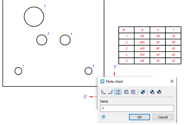
The Tables of holes tool now constructs the left coordinate system of holes.
-
Dimensioning in UCSes is corrected.
-
Symbols for surfaces are corrected.