

Trace (Semi-Automatic Vectorization)
 This functionality is available only in the Raster module
Tracing is an interactive procedure that allows you to vectorize a raster. Tracing is based on the technology of local recognition of raster geometric entities. Using this technology, the program identifies raster lines as a line, arc or circle and generates the corresponding vector objects. You specify raster on the image, and the program creates vector objects that approximate the selected raster images. As a result of tracing, a vector copy of the raster object is created.
When tracing, you have the ability to transform and place only selected objects on different layers, as well as obtain vector objects with lineweights that depend on the width of the raster line.
Tracing is performed only on monochrome raster images.
The trace order:
· configure tracing parameters;
· select the tracing mode;
· select the method corresponding to the object being vectorized;
· specify object in the image.
During tracing, local recognition of vector objects on a raster image occurs. For correct identification of objects, the program always uses two numerical parameters that determine the maximum width and value of the ignored raster line break, as well as the parameter that sets the degree of acceptable deviations of the shape of raster objects from vector prototypes.
Trace is configured in the Conversion Options dialog box, in the Options and Trace tabs.
Best parameters when configuring trace
Set the values of parameters by entering them in the appropriate fields or measure them directly in the image by pressing the ruler button.
Click OK.
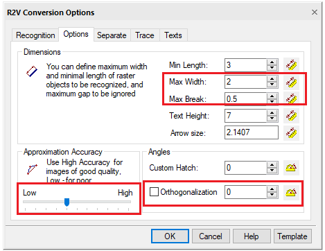
Options tab
Trace configuration options
|
Option |
Description |
|
Min.length |
Minimum size of raster object, which is analyzed by recognition algorithm. |
|
Max. Width |
Sets the maximum width of raster lines, which can be approximated by lines, arcs, circles. If the width of a raster line exceeds the Max. Width value, trace is possible only in the Auto mode with approximation by a boundary object. |
|
Max. Break |
Specifies the length of the maximum ignored break of raster lines. If the raster line is split into several parts in the image, and you need to trace this line as a single object, set the Max. break slightly larger than the maximum spacing between parts of a raster line. The program will remove the gaps and create one vector object that approximates the entire raster line. By setting a sufficiently large value of the parameter, you can, for example, trace dash-dot raster lines, arcs and circles as a whole. Values of Max. thickness and Max. Break can be entered from the keyboard or measured on the screen. |
|
Accuracy |
This parameter determines the accuracy of approximating the original raster object with a vector one. If the original image is distorted (for example, circles have the shape of an ellipse), then the value of the Accuracy parameter should be decreased. In this case, however, recognition inaccuracies may arise - for example, the program may take a short arc as a segment. Applying a smoothing filter before tracing improves the quality of the raster image. If the quality of the raster image is good, the value of the Accuracy parameter can be increased. |
|
Orthogonalization |
When this box is checked, tracing in Auto and Line modes aligns the created lines perpendicular or parallel to the base direction, if the object deviation from these directions is insignificant. The base direction is set in the parameter field. Enter the angle determining the base direction of orthogonalization - or – click the button and specify two points in the image - the value of the angle between the lines connecting these points and the direction of the X axis will be shown in the field. The value of the acceptable deviation is determined automatically by the Accuracy parameter value. |