

UTILITIES
 Main menu: Construction - Utilities -
  Create hatch.
Toolbar: Utilities - Create hatch.
 Command line: SPHPATTERN.
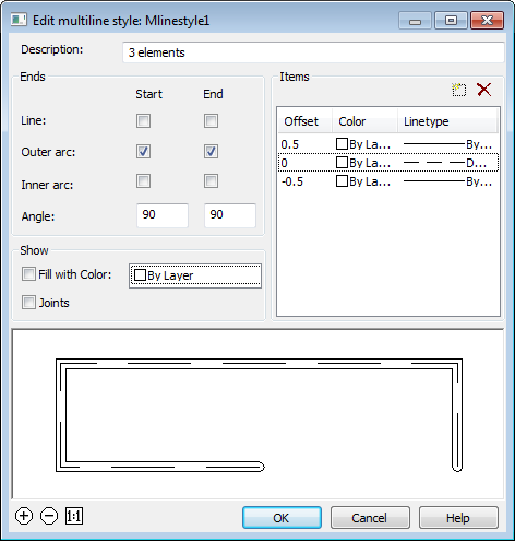
In nanoCAD Construction 23 it is possible to create hatches according to a given pattern - a sketch using the "Create hatch" tool. The hatch pattern created with it is written as an independent * .pat file and can be used in other projects or by other users.
1.Create a border for the hatch sketch. Construct a 300x300mm rectangle and place its bottom-left corner at the origin of coordinate system 0,0,0. The sketch area must be at the origin of the coordinate system. Overall dimensions of the sketch area should not be more than 300x300mm.

2. Sketch one element of the future hatch. The sketch needs to be done within the created rectangle. The sketch should only be done with lines. It is not allowed to sketch with arcs, circles. It is recommended to approximate curved objects in polylines without arc segments. Sketch polylines must be exploded into line segments.
3. Assign a different color to each section of the sketch. The sketch should be done with segments of different colors. The hatch tool recognizes the periodicity in the sketch by the color of the lines.
4. Create an array of sketches within a rectangle. The sketch must follow an explicit periodicity. The sketch must include at least three repeating fragments of the future hatching.

5. Call the command "Create hatch".
6. Create an array of sketches within a rectangle. The sketch must follow an explicit periodicity. The sketch must include at least three repeating fragments of the future hatching.

7. Press the "Enter" key. The process of object recognition and analysis will begin. During recognition, gaps in sketch lines are automatically determined, if in the selected pattern the line break is outside the selection boundary, the line will be defined in the hatch as continuous. If the sketch does not meet the conditions, a message box will appear, otherwise the file save dialog.
8. Correct the errors indicated in the message. Repeat step 5 - step 7.
9. In the file save dialog specify the path to the hatch file.
|
Important! |
You cannot use the names "Acad.pat", "Acadiso.pat" as the name of the sample file. It is recommended to save in C:\ProgramData\Nanosoft\nanoCAD Construction 23\SHX |
10. The custom hatch will be created. The hatch created with the "Create hatch" tool fully accepts all the properties of the nanoCAD hatch: associativity, the ability to change the scale, the angle of inclination, overlay with a closed tolerance.
|
Important! |
A drawing file * .dwg that used a unique hatch must be transferred to another user along with the * .pat file of the hatch pattern. For a successful translation, use the (eTransmit) "Generate Set" command. |
Main menu: Construction - Utilities -  Objects numeration.
Ribbon: Construction - Utilities - Objects numeration.
Toolbar: Objects numeration (on toolbar "Utilities").
Command line: SPNUMOBJ.
The command finds all specified objects with attributes and numbers it according to a given algorithm.
1. Call the team. The "Object Numbering" dialog opens.

2. Select objects. Select an object using the quick selection. All objects that have text editable attributes (block, database object, universal marker, etc.) can be selected.
After selecting an object, a list of attributes common to the selected objects and available for editing is formed.
Additional list management commands:
 Set selection - the command allows you to specify objects in the drawing.
 Reset conditions - command clears the list of conditions.
3. Select the attribute in which the result of numbering will be recorded.

4. Select the numbering method:
 - from left to rigth, from top to bottom. When choosing this method, the command compares the coordinates of points X and Y, respectively, starts numbering from the highest and leftmost objects to the lowest and right relative to the base point.
 - from bottom to top, from left to right. When choosing this method, the command compares the coordinates of points X and Y, respectively, starts numbering from the lowest and leftmost of the entire object to the highest and right relative to the base point.
 - from rigth to left, from top to bottom. When choosing this method, the team compares the coordinates of points X and Y, respectively, starts numbering from the topmost and to the right of the entire object to the lowest and leftmost relative to the base point.
 - from bottom to top, from right to left. When choosing this method, the command compares the coordinates of points X and Y, respectively, starts numbering from the lowest and most right of the entire object to the highest and left relative to the base point.
 - radial anticlockwise. When choosing this method, the command compares the coordinates of points in the polar coordinate system, the distance from the center (specified by the user base point) and the angle between the zero direction (positive X-axis direction). Numbering is counterclockwise. When this method is selected, the selection of the base point becomes available.
 - radial clockwise. When choosing this method, the command compares the coordinates of points in the polar coordinate system, the distance from the center (specified by the user base point) and the angle between the zero direction (positive X-axis direction). Priority in comparison has an angle. Numbering is clockwise. When this method is selected, the selection of the base point becomes available.
 - spiral anticlockwise from center. When choosing this method, the command compares the coordinates of points in the polar coordinate system, the distance from the center (specified by the user base point) and the angle between the zero direction (positive X-axis direction). Priority when comparing has distance from the center. The numbering is counterclockwise from the center. When this method is selected, the selection of the base point becomes available.
 - spiral clockwise to center. When choosing this method, the command compares the coordinates of points in the polar coordinate system, the distance from the center (specified by the user base point) and the angle between the zero direction (positive X-axis direction). Priority when comparing has distance from the center. Numbering is clockwise to the center. When this method is selected, the selection of the base point becomes available.
5. Indicate a base point if necessary. The base point is indicated either by entering the X and Y coordinates, or by pointing to the screen. When cocking the "Specify point" checkbox, the point is indicated after pressing the "OK" button.

6. Customize the brand. The formation of the brand comes from three parts. The prefix and suffix is specified in the editable field. And the brand value itself is calculated based on the initial value entered by the user and the step between subsequent values.
7. Click "OK."
8. If the "Specify point" checkbox has been set, specify the base point in the drawing.
9. Numbering will be made.
Main menu: Construction - Utilities -  Measure.
Ribbon: Construction - Library objects - Measure.
Toolbar: Measure (on toolbar "Utilities").
Command line: SPMEASURE.
Measurements or tool with Mark drawing is designed to extract various properties of objects in the drawing.
After selecting the command a dialog box value picker opens.
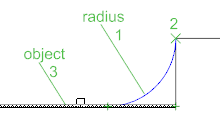
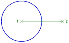
 Measure distance. Measures the distance between two points, radius or diameter. Switching the measurement method is via the context menu.
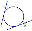
 Measure angle. Measures the angle.
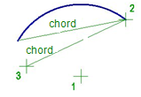
 Measure Perimeter. Measure the perimeter of the closed area, the length of a closed polyline or circle.
 Measure area. Measures the area of the closed area. Select an area in two ways: 1 - Click inside the closed loop, 2 - Click on the closed polyline or circle.
 Complex area. Measures the area of several loops. Selecting the area is carried out: 1 - Click to specify the first closed loop, 2 - Click to specify the second closed loop 3 - Press Enter to complete the command.
 Take from property. Allows you to get the value of the parameter selected in the drawing object nanoCAD Construction 23.

 Take from text. Returns the value of the selected single-line or multi-line text.
 Calculate. Opens calculator.
 Take from notes. Opens the notebook.
The measured values are displayed in the dialog box.
If universal measuring time was part of a command (for example, the dialog box nanoCAD Construction 23 text context menu command), the measured value is transmitted to the command being executed.
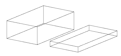
Main menu: Construction - Utilities -  Fragment copy.
Ribbon: Construction - Utilities - Fragment copy.
Toolbar: Fragment copy (on toolbar "Utilities").
Command line: SPCOPY.
The command is used to create remote views of the drawing.
1. Select the drawing center point for the detail view.
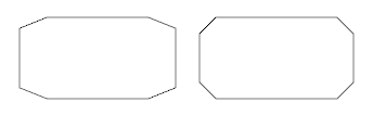
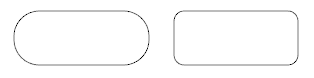
2. Select the area of the drawing. In the context menu, you can choose a certain kind of marquee - circle or rounded rectangle. Secure selection click.
3. Specify the drawing center remote fragment. available in the context menu command "0-cut" to remove the original objects from the drawing.
Main menu: Construction - Utilities -  Plate array.
Ribbon: Construction - Utilities - Plate array.
Toolbar: Plate array (on toolbar "Utilities").
Command line: SPPLTARRAY.
Command to tile layouts for a given circuit.
1. Choose from a base tile pattern and place it on the drawing.
2. Press the plate array.
3. In the opened window, click the plate shema and specify the token group.
4. Select Trim mode extreme tiles .
· Trim plates by area border - tiles clipped to the boundary of the layout. Circuit tile becomes open. This tile is taken into account in property "Cut". This mode is not available if you enable the check box "Make each tile a separate."
· Include trimmed plates - extreme tiles stacked atop circuit layout.
· Exclude trimmed plates - tiles, overlapping circuit layouts do not fit.
· Sect border type face- if tiles have execution end elements will be selected most podhodyaeschee. When the layout of the area selected by the execution system names: Whole, Left, Right, Top, Bottom. When the layout along the border all versions checked sequentially, regardless of names.
|
Trim plates by area border |
Include trimmed plates |
Exclude trimmed plates |
Sect border type face |
|
|
|
|
|


5. Create each plate as a separate object.
If the box is checked, the result will be a group of independent layout objects - copies of the original objects. This mode does not support cutting elements on the boundaries of the area, but allows more flexibility to edit the result.
When the check box is created off a single object that includes all geometry. In the properties of this object will be information on the number, weight and costs of each type of tiles, as well as the total weight (based on the whole tiles) and cost. You can delete individual tiles by clicking on them with the right. In this case the total amount will be adjusted, weight and cost.
6. Determine the work area tiles.
· auto detect - layout area defined contour, which is located inside the tile pattern. In the inner islands stacked tiles will not.
· magnet - loop selection tool "magnet".
· select - area layout is selected in the drawing indicating one or more loops.
· border - tiles splits along the perimeter or primitives nanoCAD. Cropping mode in this case will simulate laying curbs.
7. To complete the command, press OK.
|
Note: |
Creating a template tile layouts can be done using Object Wizard. |
Main menu: Construction - Utilities -  Array.
Ribbon: Construction - Utilities - Array.
Toolbar: Array (on toolbar "Utilities").
Command line: SPARRAY.
Replication called ordered distribution of copies of objects by step and quantity. Duplication of graphics in the nanoCAD Construction 23 is performed using a dialog box arrays.
Four tabs in the Arrays dialog box define four (4) different object replications.
· Arrays along an arbitrary path
For the distribution of objects within a specified area used for an array field .
Arrays along an arbitrary path(Trajectory)
1. Tab Path enter the governing parameters.
2. Follow The selection object (object selection).
3. Specify the base point.
4. Select trajectory.
5. Follow View .
6. Click OK to complete the command.

At the top of the window is a group of controls placement, which allows you to select:
· Quantity;
· Copy step;
· Base point;
· Step correction;
In the drop-down list make a choice of Overlap:
· Transparent objects;
· Next under preceding;
· Next Over preceding;
· Interleave.
Button  pick from drawing step allows you to select copies of the objects in the drawing.
Switch Show hidden line controls the display of hidden lines in the drawing. If the switch is on the hidden lines are displayed in the drawing.
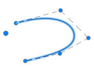
Switch Rotate copies controls the orientation of the copied object. If the switch is on when copying objects are rotated so that the vector Y was directed perpendicularly to the path (as shown in the figure).
Button  Selection to select the replication object in the drawing.
Button  from the base to select the object from the database replication of standard elements.
Button Base point lets you choose the base point of duplicated object (normally it should be expressed in the center or corner of the object).
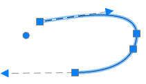
Button select a trajectory to select a graphic object, along which you will be replicating. As the trajectory can be used lines, polylines, arcs, circles.

1. Tab Arc enter the governing parameters.
2. Follow The selection object (object selection).
3. Select Center array.
4. Follow Preview .
5. Click OK to complete the command.

At the top of the window is a control group accommodation, which lets you choose placing of replicated objects:
· By number and step;
· By number and angle;
· By step and corner;
In the input field Number specify the number of replicated objects.
In the entry field Step Angle enter the angle between the replicable elements.
In the input field angle specify the angle required.
Button  with Mark drawing step allows you to select the corner or angle with the drawing.
In the drop-down list make a choice of Overlap:
· Transparent objects;
· Next under preceding;
· Next over preceding;
· Interleave.
Switch Show hidden line controls the display of hidden lines in the drawing. If the switch is on the hidden lines are displayed in the drawing.
Button Selection to select the replication object in the drawing.
Button insert from database used for selecting a center point which the objects will be replicated.
Button array center used for selecting a center point which the objects will be replicated.
Switch Rotate copies controls the orientation of the copied object. If the switch is on the turn when copying objects are shown in the figure.

1. Command Rectangle enter key parameters.
2. Follow The selection object (object selection).
3. Follow Preview .
4. Click OK to complete the command.

Enter the number of objects in the array horizontally and vertically, to specify the amount of horizontal and vertical steps between objects.
1. Tab steps enter the governing parameters.
2. Follow The selection object (object selection).
3. Follow > View .
4. Click OK to complete the command.
Enter the number of objects in the array, specify the amount of horizontal and vertical step between objects.

Main menu: Construction - Utilities -  Area array.
Ribbon: Construction - Utilities - Area array.
Toolbar: Utilities - Area array.
Command line: SPARDARRAY.
The tool is designed to replicate objects within a given area.
1. Call the command "Area array". A dialogue will open "Area array".

2. Click the "Object(s)" button and select the original objects to copy in the drawing. Press the "Enter" key to complete the selection.
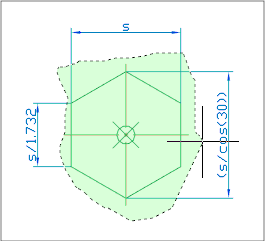
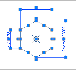
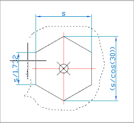
3. Select the method of placing the copied objects using the graphic switch:
 - Rhombus.
 - Square.
 - Triangle.
4. Specify the spacing (H) between adjacent copies. The "Pick from drawing" button allows you to select a step from the drawing.
5. Specify the minimum indent (?) from the edge of the area. The "Pick from drawing" button allows you to select an indent from the drawing.
6. Set the area of the array in one of three ways:
·  "Select an area by the point". The construction area is formed from a set of closed areas. The command allows you to add closed areas to the set by clicking the LMB inside a closed contour in the drawing. Clicking again inside the contour removes the selected area from the set. To complete the selection, press the "Enter" key.
·  "Select contour with the magnet". The contour of the array area is set using the utility "Magnet".
·  "Paint area". The command allows you to specify an arbitrary placement of copied objects, providing a set step between adjacent copies. This command is available only after selecting the source objects to copy.
The construction of the area is carried out by moving the mouse cursor over the drawing (construction must be started from the location of the original objects). As you move the cursor, markers will appear on the screen to indicate where the copied objects are inserted.
To remove insertion markers, press and hold the "Shift" key. When you hover over a marker, the marker will be deleted.
To temporarily disable the placement of markers, press and hold the "Ctrl" key.
Finish drawing the area by clicking LMB. An array by area will be built.
7. Click the "OK" button. An array by area will be built.
Main menu: Construction - Utilities -  Centerlines.
Ribbon: Construction - Symbols - Centerlines.
Toolbar: Utilities - Centerlines.
Command line: SPAXIS.
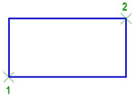
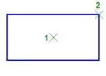
The command is designed to draw centerlines.
The construction method depends on the selected objects:
· Parallel lines. The centerline will be drawn in the middle between these segments.
1. Call the command "Centerlines".
2. Select the first line.
3. Select the second line.
4. Specify manually the first point of the centerline or press the "Enter" key. When you press the "Enter" key, the centerline is drawn automatically with a protrusion specified in the settings (by default 2mm).
5. Specify manually the second point of the centerline or press the "Enter" key. When you press the "Enter" key, the centerline will stop drawing, the second point will be in the calculated center between the lines.
In the case of manual selection of the start / end point of the centerline, the amount of the protrusion is controlled by the user.

· Non-parallel line segments. The centerline will be drawn along the bisector of the angle between the line segments.
1. Call the command "Centerlines".
2. Select the first line.
3. Select the second line.
4. Select the direction of the centerline. Using the "Rotate" context menu command, you change the direction of the centerline drawing (available only for intersecting line segments).
5. Specify manually the first point of the centerline or press the "Enter" key. When you press the "Enter" key, the centerline is drawn automatically with a protrusion specified in the settings (by default 2mm).
6. Specify manually the second point of the centerline or press the "Enter" key. When you press the "Enter" key, the centerline will stop drawing, the second point will be in the calculated center between the lines.
In the case of manual selection of the start / end point of the centerline, the amount of the protrusion is controlled by the user.

· One circle. Draws centerline centerlines on the selected circle.
1. Call the command "Centerlines".
2. Pick a circle.
3. Press the "Enter" key.

· Two or more circles. Draws centerline centerlines on selected circles with one common centerline.
1. Call the command "Centerlines".
2. Select the first circle.
3. Select the second circle.
4. Press the "Enter" key. If on the line between the centers of the two selected circles there are also centers of other circles, then for such circles, axial ones will also be built.
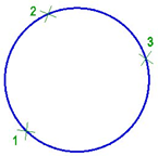
· Three mismatched circles. Creates a circle of centers passing through the centers of the selected circles. Center axes are automatically added to all circles whose centers coincide with the constructed center circle.
1. Call the command "Centerlines".
2. Select the first circle.
3. Select the second circle.
4. Select the third circle.

Main menu: Construction - Utilities -  Fillet.
Ribbon: Construction - Utilities - Fillet.
Toolbar: Fillet (on toolbar "Utilities").
Command line: SPFILLET.

 Pick from drawing
 Mode full trim contour lines
 Mode partial trim lines to their intersection
 Mode without cutting
 Copying properties
 Measure fillet. Tabulated fillet radius and the number
 Extra measurement. Stamped dimensions of the original geometry. Active only when the button "dimensioned pairing"

 Insert circle as fillet.
Double click the left mouse button or click the right mouse button in the input fields of values, a context menu will open with a list of the last entry:

When a command from the context menu, the following options::
properties - Open the dialogue to change the chamfer .
new - Completion of a group of facets and the beginning of another. This command is used when you need to, for example, several facets of the same size on the same site, and then with the same dimensions - on the other:
Chamfer - Switch to build Circle. After you select the shortcut menu command opens this dialog Pairing parameter setting interface.
polyline - Switching to chamfering along the selected polyline. This option is available if you have selected the type of symmetric Circle: one length or two identical length. In operation, the cut-off modes are ignored and dimensioning.
Command works in 3D. To execute the command source primitives must lie in one plane
If you select the second object, press and hold SHIFT, then the angle will be formed (at the intersection of the closure and isolation).
For a pair of ARC-ARC additionally available pairing, combining internal and external touch.


For a pair of ARC-ARC additionally available pairing, combining internal and external touch.
Availability of different types of interfaces depends on the fillet radius. To the outside and combining the radii need greater magnitude than the inner.
When two parallel lines will be constructed pairing radius equal to half the distance between them (regardless of the specified length). Automatically aligns the sides to the longest segment. When two parallel lines will be constructed pairing radius equal to half the distance between them (regardless of the specified length). Automatically aligns the sides to the longest segment.
Pairing works parallel segments and regions of the same polyline.
Side interface depends on the position of the mouse cursor when the second object
When you insert a polyline retains its integrity.
If the team is formed of two polylines one, it will be object of a single polyline.
If you select one polyline segments separated by other sites, all the intermediate portions are removed.
Main menu: Construction - Utilities -  Chamfer.
Ribbon: Construction - Utilities - Chamfer.
Toolbar: Chamfer (on toolbar "Utilities").
Command line: SPCHAMFER.
This command is used for automatic and semi-automatic placement of face on the details with the various versions and with the possibility of automatic dimensioning.
After clicking the command, it opens a dialog box settings Circle:
 Mode chamfering parts with two different sizes


 Mode chamfering parts with two different sizes


 Mode Chamfer length and angle in this mode instead of the length 2 displays the setting angle.


 Mode full cutting contour lines
 Mode partial cutting lines to their intersection
 Mode without cutting
Measure Chamfer
Copy properties surrounding face
Pick from drawing
Double click the left mouse button or click the right mouse button in the input fields of values, context menu will open with a list of the last entry:

When a command from the context menu, the following options:
Propertise - Opening the dialogue to change the chamfer chamfer.
New - Completion of a group of facets and the beginning of another. This command is used when you need to, for example, several facets of the same size on the same site, and then with the same dimensions - on the other:
Fillet - Switch to build pairings. After you select the shortcut menu command opens this dialog Pairing parameter setting interface.
Polyline - Switching to chamfering along the selected polyline. This option is available if you have selected the type of symmetric Circle: one length or two identical length. In operation, the cut-off modes are ignored and dimensioning.
The command works in 3D. To execute the command source primitives must lie in one plane.
If you select the second object, press and hold SHIFT, then the angle will be formed (at the intersection of the closure and isolation).

When you insert a polyline retains its integrity.
If the team is formed of two polylines one, it will be object to a single polyline.
If you select one polyline segments separated by other sites, all the intermediate portions are removed.


Main menu: Construction - Utilities -  Anchor.
Ribbon: Construction - Symbols - Anchor.
Toolbar: Utilities - Anchor.
Command line: SPANCHOR.
The command is intended for drawing end markers on line segments.
1. Call the command "Anchor". A dialogue will open "End markers of lines".

2. In the "End markers of lines" dialog select the type of end markers and set their parameters. Click the "OK" button.
3. Specify the necessary lines or polylines in the drawing. "End markers" objects are created from from. Press the "Esc" key to end the circular mode for specifying objects.

The "End markers of lines" editing dialog contains:
The panel of tabs for selecting marker types.
The "Reinforcing markers" tab allows you to define reinforcement markers.

To change, select a marker for the first or second end of the segment by clicking on the graphics field (the button with the reinforcement marker image) and selecting one of the following options:
The "Arrows" tab allows you to define arrows.

To change, select the arrow for the first or second end of the line segment by clicking on the graphic field (the button with the arrow) and choosing one of the following options:

"Size of marker" group
Input fields "A1", "A2", "B1", "B2" - allow you to specify the corresponding sizes of markers in the current scale nanoCAD Construction 23. The fields used are indicated on the image of the markers.
Group "Line weight of marker"
Drop-down list "Line weight" - allows you to select the line weight of markers.
Additional commands
The  "Copy Properties" button - allows you to copy the appearance of end markers and their dimensions from a line with reinforcement or arrow markers in the drawing.
Main menu: Construction - Utilities -  Hole group.
Ribbon: Construction - Symbols - Hole group.
Toolbar: "Utilities") - Hole group.
Command line: SPFILL.
Universal command for drawing holes. With its help, you can draw a new hole with centerlines, or by specifying a group of holes to assign them general properties with filling of a sector.
1. Draw holes from circles.

2. Call the command "Hole group".

3. Select the required circles. Press the "Enter" key to complete the selection. The "Holes" dialog will open.

4. Adjust the hole settings and click "OK". The parameters will be applied to the holes. The holes will be created.

The "Holes" editing dialog is opened by double-clicking. The dialog consists of: Toolbar, Parameter List, Graphics Window.
Toolbar
Match properties - this command allows you to copy parameters from holes already installed in the drawing.
 Select holes - the command allows you to select additional holes from the drawing.
 Create holes - the command creates holes of the specified diameter. To dynamically set the radius on the screen, hold down the left mouse button and move the cursor.
Parameter List
Designation
· Number - specifies the number of the hole in the group.
· Description - specifies the hole table description field.
· Standard - sets the field to the standard of the hole table.
· Roughness - allows you to specify the roughness of the hole (displayed in the hole table).
Dimensions
· Diameter - hole diameter.
· Tolerance - the "..." button opens the "Tolerances" dialog, from which you can select a tolerance.
· Thread pitch - hole thread pitch.
Representation
· Hole - hole display switch.
· Label - label display switch.
· Axes - axis display switch.
· Threaded hole - thread display switch.
· Diam. dimension - diametrical dimension display switch.
· Center identifier - drop-down list for selecting the hole center designation.
|
Note: |
Also, the parameters of the "Representation" section can be configured through the graphics window. |
Graphics Window
The graphics window allows you to see the resulting hole representation and customize the representation by directly specifying elements.
|
Threaded hole |
Axes |
Fill first quarter |
|
|
|
|
|
Fill second quarter |
Fill third quarter |
Fill fourth quarter |
|
|
|
|


The parameters on the "Properties" functional panel are similar to the parameters from the list of parameters of the "Holes" dialog.
1. Hole position change grip.
2. Diameter change grips.
3. Grip for changing the position of the hole number.
4. Hole rotation grip.
5. View adjustment grip.
Main menu: Construction - Utilits -  Static beam calculation.
Toolbar: Calculation beams (toolbar "Utilits").
Command line: SPBEAM.
 Library: Calculations - Loads - Beam.
Library: Calculations - Loads - Calculations - Beam calculation (applied to the finished beam affixed to the supports, loads and moments, see. Calculation).
This command is used to calculate the strength of the direct beam of constant cross-section.
After selecting the command a dialog box opens beam calculation.
1. On the left side of the dialog box, select the cross-section of the beam.
2. Right set sectional dimensions and length L beams. For visual selection of the beam length, click  Dynamic input at the bottom of the dialog box.
3. Enter the physical characteristics of the material and the cut rotation.
4. Specify moment and the loads acting on the beam.
There are three ways to specify the section:
|
|
|


For the standard section of the database items, choose Type size from the dropdown list.

1. In the dialog box, double-click the desired type of load or moment.
2. Select insertion point or the load bearing on the beam. At the time of selecting the insertion point move the cursor to the beam to install dependencies.

3. Set the parameters or load bearing in the dialog box.
· Support
Point - the distance from the starting point to the point of insertion beam bearing in millimeters. Use keys to select the type of support.
· Concentrated load
Position - the distance from the starting point to the point of insertion beam load, mm.
Value - the value component of the load in the selected direction, H.
Point - the distance from the insertion point to the point of load application of the load in the selected direction, mm.
Diagram on the left side of the dialog box explains the meaning of the input parameter.
Tabs on the top of the window are used to select the coordinate system in which the values are set:
 Rectangular
 Spherical
 Cylindrical
· Distributed load
Position - the distance from the starting point to the point of insertion beam load, mm.
Length - length of the section, which is attached to a distributed force, KN/mm.
In input fields, set the value component of the load in the selected direction, H.
Diagram on the left side of the dialog box explains the meaning of the input parameter.
Tabs on the top of the window are used to select the coordinate system in which the values are set:
Rectangular
Spherical
Cylindrical
· Moments
Diagram on the left side of the dialog box explains the meaning of the parameters.
X, Y, Z - the components of the bending moment , KN*m.
C - distance from the starting point to the point of insertion beams torque , mm.
Click  Calculate beam at the bottom of the dialog box to perform the calculation.

Table of results of calculating comprises calculating the maximum deflection and stress values as well as the distance from the starting point of the beam to a point at which the maximum of each parameter.
To insert a drawing graphs strain and effort to select the desired type of graph for each feature:


Button  Apply adds graphics drawing.

Button  Save Report. Stores the results of the calculation of the beam to an external file.
Button  Calculate value. Opens Meaning, in which parameters are calculated at an arbitrary point of the beam.

Button 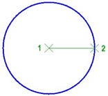 Export diagrams. Sell calculation results in a table in Construction Site 23. After selecting the command, specify the insertion point on the drawing table.
Calculate section characteristics
Main menu: Construction - Utilits -  Calculate section characteristics.
Toolbar: Calculate section characteristics (toolbar "Utilits").
Command line: SPGCS.
This command is used to calculate the geometric characteristics of the complex cross-sections with respect to arbitrary axes.
1. Call command.
2. In the drawing, then click the area closed by one of the ways:
· Clicking inside a closed area. Automatically determined by the outer loop of the closed area, and the area is added to the set.
· Clicking on a closed polyline or circle. Adds the area bounded by polyline or circle.


|
Note: |
Repeated selection of the field deletes it from the set to calculate the cross-section. |
3. Complete the selection by clicking the right mouse button or the Enter key.
4. Specify the origin point or [central axis]. If you select the "central axis", the point of origin is automatically set in the center of mass of the cross section with an angle of rotation equal to 0 (step 5 is skipped).
5. Specify the angle of rotation of the coordinate system.

6. In the dialog box "Geometric section properties" Adjust the characteristics included in the summary table of the results.
For each characteristic, you can customize your format (except weight), and the accuracy of the unit.

To calculate the weight you need to open an additional menu "Mass calculation on section", which indicate the product density and length. When you specify the length of the need to expose the units. When you specify the density, you can use the base materials, by clicking on the button  "Material selection".
Customized settings display characteristics (size, precision, units) stored for later calculations sectional characteristics. To return to the default settings, press the button 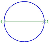 "Load default settings".
7. Click "OK" in the dialog box and enter the drawing an insertion point of the table with the calculated parameters.

After the calculation is added to the drawing object nanoCAD Construction 23, comprising a cross-section schematic outline and the main central axis. The lengths of the axes are proportional to the values of the corresponding axial moments of inertia.
The calculator is designed for complex mathematical calculations. The capabilities of the table and text editor are significantly expanded using the powerful functionality of the calculator.
The calculator is available in the table editor, text editor, when using the "Inquiry" utility in the "Value picker" dialog.
The "Calculator" dialog consists of a main menu and a set of grouped commands.

Main menu
· Edit
· Copy Ctrl+C - the command copies data from the input field.
· Paste Ctrl+V - the command pastes the copied data into the input field.
· View
· NoteBook - command opens the notebook panel.
· Degrees - the command switches the mode of calculating angles in degrees.
· Radians - the command switches the mode of calculating angles in radians.
· Expression - the command turns on the formula calculation mode. The input field is divided into two: on the left is the formula, on the right is the result.
Commands
Drop-down list "Precision" - sets the rounding digit of the calculation result.
Switch "Degrees - Radians" - switches the angle calculation mode.

Group of buttons "Mathematical operations".

The main group of calculator buttons. The composition of the buttons is similar to all standard calculators.

Buttons for navigating table cells. Available when editing a table cell. It also shows the name of the currently edited cell.

Button  to open the "Notebook" sidebar. It is possible to connect the spreadsheet editor of the "Notebook" tool. The additional sidebar lists tables from the notebook in a drop-down list. After selecting a table, its composition will be displayed. Double-clicking on a value from the table adds this value to the input field. This tool is useful when you need to perform routine calculation activities frequently.

The "Insert" button is designed to insert the result of calculations from the calculator into an editable cell, a text entry field or the "Value picker" dialog.
The "Close" button closes the calculator dialog without transferring the value.
Insert material designation to the table
Button  material designation.
This tool is designed to be inserted into the table, the technical requirements and specifications of the formatted string records on material and product mix. By pressing the button, a dialog box appears called material designation.

Button Notebook
To enter recurring standard text expressions (abbreviations, symbols, etc.) used tool Notebook. This is a versatile tool for some editing tools nanoCAD Construction 23, which is necessary to enter text. Notebook combines the functions of: storing a set of expressions and the structure of their placement in a separate file, input and placement of text expressions, input and placement of small tables, searching and editing tools introduced earlier records.
Dialog Notebook divided into two parts. On the left side there is a tree structure of the notebook where the user selects the sections and pages notebook. In the upper part of the window control buttons notebook.
 Load from file. Opens the notebook file stored on disk.
 Save. Saves the changes to the file in your notebook.
|
Important! |
Recommended that you save a new notebook in a separate file in the first call to the tool Notebook using the button Save. |
To search for a text string in a notebook has a special search tool, Right-click on any section or page of the section and in the context menu, call the command Find. Found links are placed in the section  results
To accelerate the search procedure provided for viewing the latest expressions used in section  history.
Management structure for the notebook with the buttons:
 Add a partition
 Add this page
 Add a table
 Delete tree item
In the notebook is allowed to create an unlimited number of sections and subsections, pages, and tables.

Moving sections, pages, and tables for structural wood can produce a drag and drop (drag and drop).
Rename the selected section or page using the command Rename the shortcut menu.
 Select / Copy the selected text. Transmits the selected piece of text pages into editable table cell. If the tree structure of the selected page or table in your notebook, the contents displayed on the right side of the dialog. Highlight the desired entry cursor, and turn the Select / Copy the selected text.
 Edit Page. This button is used to activate the edit pages and style notebook. It becomes active only if the tree structure is selected page element or table. In edit mode, the tree structure becomes inactive, and the right side activates the Edit toolbar.
 Editing tools page
|
|
Switch controls the display of the slash.
|


 Tools for editing table
|
|
|
After editing, when you exit the notebook dialog appears - prompted to save the changes in a notebook.
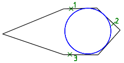
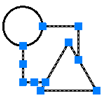
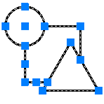
Magnet used to draw complex paths based on existing graphics. The contour can be constructed by points or by sequential indication of adjacent segments or arcs.
Called by:
· from the context menu (Weld seam, Simplified weld joint, Bound forms)
· button "Select contour with the magnet" in the dialog (Area array).
An example of constructing a weld seam contour, based on an I-beam image inserted into the drawing
1. We call the command 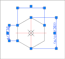 "Weld seam". A dialogue will open "Weld seam".
2. Select the type of seam and click "OK".

3. In the context menu, select the command "Magnet".

4. We indicate the starting point of the contour.
5. Sequentially move the cursor over the end points of the linear and arc sections of the I-beam contour.

Deselection of the previous segment is made by re-pointing the cursor to the starting point of this segment or by the "Back" command from the context menu.
6. Use the "Close" command from the context menu to complete the construction of the closed contour.
7. The weld will be built along the specified contour.

Command line: SPADDCOPY.
The command allows you to create a new object nanoCAD Construction based on the type and general properties of the selected object nanoCAD Construction .
1. Call the command "Add selected" - ADDCOPY.
2. Press the "Space" key (the <Multiple> option will turn on) if you want to insert the object in a cyclic mode.
3. Select an object to serve as a template. The paste command for the selected object type will run. The properties of the new object will match the template object.