

-
-
-
-
-
-
-
-
-
-
-
-
-
-
-
-
-
-
-
-
-
-
-
-
-
-
-
-
-
-
-
-
-
-
-
-
-
Model space and paper space
-
-
-
-
-
-
-
-
-
-
Model space and paper space
The main working environment in nanoCAD is the model space intended for creating and editing objects.
Paper space is an auxiliary workspace that assembles various views created in model space for plotting. In paper space you can create various entities that will belong only to paper space, but will not be displayed in model space. Such objects are, for example, a format frame and main and additional titles, technical requirements, specifications, inscriptions, tables and other text and graphic information necessary to plot a drawing.
To transfer information from model space to paper space, it is necessary to create a viewport. A viewport is a kind of window from paper space to model space that displays some preset portion of model space. One layout can contain several viewports with different views. The image of the configured layout on the screen looks exactly the same as after printing on the plotter. For each layout, the format (sizes of the layout sides) and print settings are set independently. The layout content is displayed according to the plot style applied to that layout. For example, if you set the plot style to monochrome in the Page setup dialog, the layout content will also be displayed in black and white.
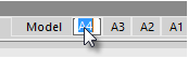
You can create multiple named layouts for a document. Tabs with layout names are located at the bottom of the document window, next to the Model tab. The Model tab and layout tabs allow you to pass to the workspace of the model or the corresponding layout. Switching between model space and created layouts is performed by clicking on the selected tab:
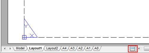
The display order of layout tabs can be changed by dragging the tabs to the left or right.
To quick switch between the model space and layouts, use the  button located at the beginning of tabs line. This button also allows you to switch between the named views available in the document. A click to the button opens a context menu that displays all the layouts and named views available in the document:
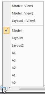
The top part of the menu displays the named views; the bottom part displays the Model layouts and space. The current space is marked with  . To switch to a desired tab or desired named view, it is necessary to click on the corresponding item in the menu. When you switch to a named view, there is auto-panning of the view on the screen.
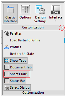
The display of layout tabs is enabled/disabled by  Sheets Tabs command located in the View menu and on the ribbon (Manage tab – Customization group).
You can rename, delete and add layout tabs unlike the Model tab. The last (the only one in the document) layout tab cannot be deleted.
Another important difference between model space and paper space is that you create non-overlapping viewports in the model space, i.e. snap-together at the boundaries. In model space you can print only the current viewport. Viewports in the paper space are floating. They can be moved to any part of the layout. Their boundaries can be close to each other and overlapped or be located at some distance from each other. You can print all the viewports located on the layout at the same time.
To work with a layout, use the command from the Insert menu – Layout item, or from the Layout toolbar, from the Layouts Manager dialog box, or from the context menu that opens by right clicking the Model tab or a Layout tab.
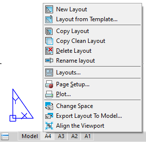
To create a new layout, use the Add Layout command. To delete a layout, use the Delete Layout command.
You can rename the current layout by double-click on its tab or by selecting the Rename layout command from the tab’s context menu:
To rename any layout in a document, use a separate LAYOUT command.
The format of the displayed layout is set in the Page Setup dialog box.
note: The print area of the layout for the current format settings and printer is displayed by a dashed line.
You can change the layout color in the Options dialog box using the Color settings item – Layout Paper.
When you prepare a layout, you typically go through the following process:
1. Create a model of your subject on the Model tab.
2. Click a Layout tab and specify layout page settings, such as plotting device, paper size, plot area, plot scale and drawing orientation.
3. Insert a title block into the layout.
4. Create a new layer to be used for the layout viewports.
5. Create the layout viewports and position them on the layout.
6. Set the orientation, scale and layer visibility of the view in each layout viewport.
7. Add dimensions and annotate in the layout as necessary.
8. Turn off the layer containing the layout viewports.
9. Execute the plot setting of the layout.
10. Plot the layout.