

-
-
-
-
-
-
-
-
-
-
-
-
-
-
-
-
-
-
-
-
-
-
-
-
-
-
Hatch Dialog Box
-
-
-
-
-
-
-
-
-
-
-
-
-
-
-
-
-
-
-
-
-
-
-
-
-
-
-
-
-
Hatch Dialog Box
The Hatch dialog box appears to select the hatch pattern and specify options:
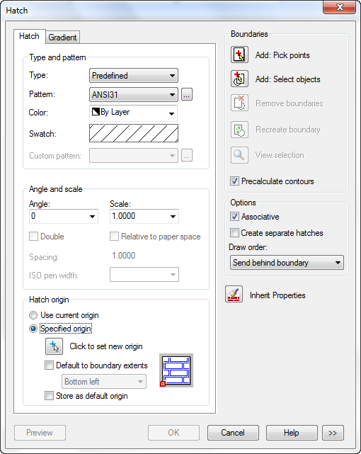
Options:
Type and pattern
|
Type: |
Drop-down list to select the type of hatch pattern: The following types are available: · Predefined · User defined · Custom |
|
Pattern: |
Drop-down list to select the available predefined patterns. The Pattern option is available only if you set the Type to Predefined. |
|
|
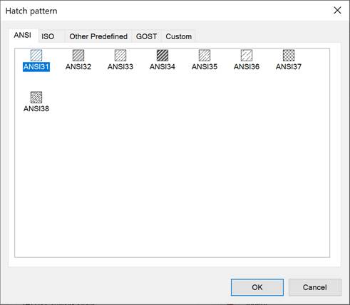
This button opens the Hatch pattern dialog box.
The dialog box contains the tabs: · ANSI – the hatch patterns of the ANSI standard; · ISO – the hatch patterns of the ISO standard; · Other Predefined – the hatch patterns that are not related to the ANSI and ISO standards; · GOST – samples of shading of materials graphic representations according to GOST; · Custom – the list and patterns of the custom file format *.pat. By default, hatch smaples are located in the C:\ProgramData\Nanosoft\nanoCAD X.X\SHX folder. You can change its location in the Options settings in the Standard Directories – Hatch Sample Files location. Custom hatch patterns are placed in the same folder. |
|
Color: |
Drop-down list to select the hatch color. |
|
Swatch: |
Displays a preview of the selected pattern. Click the swatch to display the Hatch pattern dialog box. |
|
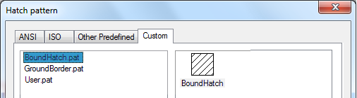
Custom pattern: |
Drop-down list to display the available custom patterns. The Custom pattern option is only available for Custom type of hatch pattern. If you select the Custom option in the drop-down Type list, the Hatch Pattern dialog box opens on the Custom tab: The available custom hatch patterns display in the left part of tab. The selected pattern displays in the right part:
The custom hatch pattern (file with *.pat extension) are placed in the folder: C:\ProgramData \Nanosoft AS\nanoCAD Int 24.0\SHX. |
|
|
This button opens the Hatch pattern dialog box. |

Angle and scale
|
Angle: |
Drop-down list to specify an angle for the hatch pattern relative to the X axis of the current UCS. Values can be input from the keyboard. |
|
Scale: |
Drop-down list to expand or contract a predefined or custom pattern. Values can be input from the keyboard. This option is only available if you set the Type to Predefined or Custom. |
|
Double |
Turns on/off the mode to draw a second hatch positioned at 90 degrees to the original hatch. This option is only available if you set the Type to User Defined. |
|
Hatch origin |
Sets the start point to create the hatch. Some hatches, such as brick patterns, need to be aligned with a point on the hatch boundary. By default, all hatch origins correspond to the current UCS origin. |
|
Use current origin |
Turns on the mode of origin setting stored in the HPORIGINMODE system variable. The origin is set to 0,0 by default. |
|
Specified origin |
Specifies a new hatch origin. |
|
|
Specifies the new hatch origin point on the screen using the cursor. |
|
Default boundary extents |
Turns on/off the mode for calculation of a new origin based on the rectangular extents of the boundary for the hatch. From the drop-down list the following options are available: · Bottom left · Bottom right · Top right · Top left · Center The icon displays the current position of the origin point:
|
|
Store as default origin |
Turns on/off the mode for saving the value of the new hatch origin in the HPORIGIN system variable. |


Boundaries
|
|
Add: Pick points |
Determines a boundary from the existing objects that form an enclosed area around the specified point. The dialog box closes temporarily and you are prompted to pick a point. |
|
|
Add: Select objects |
Determines a boundary from selected objects that form an enclosed area. The dialog box closes temporarily and you are prompted to select objects. |
|
|
Remove boundaries |
Removes from the boundary definition any of the objects that were added previously. This option is unavailable if you have not specified points or not selected objects. |
|
|
Recreate boundary |
Creates a polyline or region around the selected hatch and optionally associates the hatch object with it. This option is available when you edit the hatch. |
|
|
View selection |
Temporarily closes the Hatch dialog box and displays the currently defined boundaries with the current hatch settings. This option is unavailable if you have not specified points or not selected objects. |
|
|
Precalculate contours |
The checkbox activates the mechanism for contour preliminary search, which is used to dynamically highlight potential contours under the cursor during the procedure for adding contours by specifying an internal point ( A preliminary search for contours is carried out immediately after clicking the Add: Pick points button. The search for contours will be performed only for the drawing geometry that will be displayed in the current view window at that time. If it takes time to search for contours, a window with a progress bar will appear. The found contours are highlighted under the cursor in green, and if contours with an acceptable gap value are found (the value of the Gap tolerance field) – in red. In this case, the locations of the gaps in the contour are outlined with red circles. The process of selecting hatch areas when the preliminary contour search mechanism is enabled is described in more detail below in the Creating hatches section. |


Options
|
Associative |
Turns the associative hatch mode on/off. |
|
Create separate hatches |
Turns on/off the mode for changing a single hatch object that has several separate boundaries into individual hatch objects. When this mode is turned on, the hatch will be created for each counter, which representing a separate object. |
|
Draw order: |
Drop-down list to assign the draw order to a hatch or fill. From the drop-down list the following options are available: · Do not assign · Send to back · Bring to front · Send behind boundary · Bring in front of boundary |
|
|
Temporarily closes the Hatch dialog box to specify boundaries using the hatch properties of a selected hatch object. |
|
|
Temporarily closes the Hatch dialog box and displays the currently defined boundaries with the current hatch settings. Press ESC to return to the dialog box. |
|
|
Expands the Hatch dialog box to display more options. |


The More Options section of the Hatch dialog box:
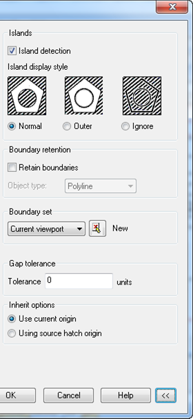
The More Options section of the Hatch dialog box:
Islands
|
Island detection |
Turns on/off the mode to detect internal closed boundaries (islands). |
|
Island display style |
Selects the island display style. |
|
Normal |
Hatches inward from the outer boundary. If the hatch encounters an internal island, it turns off hatching until it encounters another island within the island. |
|
Outer |
Hatches inward from the outer boundary. Hatch turns hatching off if it encounters an internal island. This option hatches only the outermost level of the structure and leaves the internal structure blank. |
|
Ignore |
Ignores all internal objects and hatches through them. |


Boundary retention
|
Retain boundaries |
Creates boundary objects from the temporary hatch boundaries and adds them to the drawing. |
|
Object type: |
Controls the type of the new boundary object. The following types are available: · Region · Polyline |
|
Boundary set |
Defines the set of objects analyzed when defining a boundary from a specified point. The selected boundary set has no effect when you use Select Objects to define a boundary. From the drop-down list the following object sets are available: · Current viewport - Defines the boundary set from everything within the current viewport. · Existing set - Defines the boundary set from the objects that you selected with New. |
|
|
Sets the maximum size of gaps that can be ignored when objects are used as a hatch boundary. |

Gap tolerance
|
Tolerance |
Sets the maximum size of gaps that can be ignored when objects are used as a hatch boundary. Enter a value, in drawing units, from 0 to 5000 to set the maximum size of gaps that can be ignored when the objects serve as a hatch boundary. Any gaps equal to or smaller than the value you specify are ignored and the boundary is treated as closed. |
|
Inherit options |
When you use Inherit Properties to create a hatch, these settings control the location of the hatch origin. |
|
Use current origin |
Uses the current hatch origin setting. |
|
Using source hatch origin |
Uses the hatch origin of the source hatch. |