

-
-
-
-
-
-
-
-
-
-
-
-
-
-
-
-
-
-
-
-
-
-
-
-
-
-
-
-
-
-
-
-
Mechanical Note
-
-
-
-
-
-
-
-
-
-
-
-
-
-
-
-
-
-
-
-
-
-
-
-
Mechanical Note
 Ribbon: Home, Annotate – Leaders –
  Mechanical notes
Menu: Draw – Notes >  Mechanical notes…
 Toolbar: Utilities –
 Command line: NOTE
This command opens the Mechanical note dialog box to set the mechanical note options:
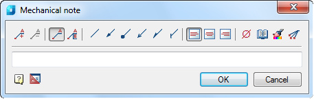
Options:
Use the icons to add/remove text input fields and to add a border:
|
|
Add string. |
|
|
Remove string. |
|
|
Simple note. |
|
|
Multiline note. |


Use the icons to select the style of the extension line:
|
|
None. |
|
|
Arrow. |
|
|
Point. |
|
|
Open arrow. |
|
|
Half-arrow. |
|
|
Oblique. |


Use the icons to select the text alignment method:
|
|
By left edge. |
|
|
By center. |
|
|
By right edge. |


Other icons and options:
|
|
The Insert special symbol icon opens the panel with the table of special symbols, to select and insert them at the current cursor position in the text input field. |
|
|
The Notepad icon opens the Notepad dialog box. |
|
|
The Match properties icon temporarily closes the dialog box to specify the inserted leader whose properties should be copied and applied to the newly-created leader. |
|
|
The Add extension line icon is used to insert additional extension lines. The icon is enabled when you edit a leader inserted into the drawing. |


Right-click in the text field and choose the required menu item:
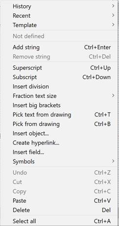
The History item contains a list of recently input text lines.
The Recent item is a list specified by the user. Upon typing the desired leader text, you can add it to the list of frequently used ones for quick reference later.
Template – connects templates.
Add string – adds a line to the leader text (a field for a new line appears in the dialog box).
Remove string – removes a line.
Superscript – inserts a superscript.
Subscript – inserts a subscript.
Insert division – inserts fractional text.
Fraction text size – selects a fraction dimension option from the list:: Default, Like the main text, One step less.
Insert big brackets – inserts parenthesis.
Pick text from drawing – inserts the text specified in the drawing into the field. If you change the original text, the universal leader text will update automatically.
Pick from drawing – allows you to select text or value in the current drawing.
Insert object... – inserts a drawing object instead of the leader text.
Create hyperlink... – creates a hyperlink.
Insert field… – inserts a field (FIELD command).
Symbols – inserts a standard symbol (degree, slope, etc.) or any symbol from the OS symbol table.
Undo – undoes the last action.
Cut, Copy, Paste – tandard operations using the OS clipboard.
Delete – deletes text from the input field.
Select all – selects all text in the input field (for example, for replacement).
The Pick from drawing item opens the Value picker toolbar which allows you to copy values from the objects on the drawing:
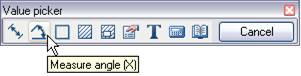
 Measure distance(Z) – take a linear or diametrical geometric dimension from the drawing. The command can be started by pressing the Z key.
 Measure angle(Х) – take an angular dimension from the drawing. The command can be started by pressing the Х key.
 Measure perimeter (С) – take the value of a closed line perimeter or the length of a broken line from the drawing. The command can be started by pressing the С key.
 Measure area (V) – take the value of the closed contour area from the drawing. The command can be started by pressing the V key.
 Complex area (Shift+V) – take the value of several closed contour areas in the drawing.
 Take from property(В) – take the parameter values of a standard nanoCAD database part. The parameter is inserted with maintaining the dynamic connection with the object. When you change a part parameter, the line in the input field changes.
note To insert static text, hold CTRL while selecting a parameter.
 Take from text(N) – take text from a drawing object.
 Calculate (M) – calculate a numerical value using the built-in nanoCAD.
 Take from notes(,) – insert text information from a notepad.
Cancel – rejecting the command and returning to the previous menu.
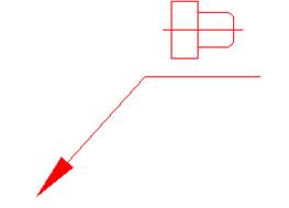
To create a mechanical note:
1. Type the required text into the text fields.
2. Select the required leader options.
3. Click OK.
4. Specify a point on the object to which the leader arrow will be directed.
The following arrow type switching options are available in the command line and context menu:
None – Creates the extension line without an arrow.
Arrow – Creates the extension line with an arrow.
Point – Creates the extension line with a point.
5. Select an option and specify the leader position on the drawing.