

-
-
-
-
-
-
-
-
-
-
-
-
-
-
-
-
-
-
-
-
-
-
Editing Objects Using Multifunctional Grips
-
-
-
-
-
-
-
-
-
-
-
-
-
-
-
-
-
-
-
-
-
-
-
-
-
-
-
-
Editing Objects Using Multifunctional Grips
Grips that can change editing mode by round robin in rotation are called multifunctional. Rotation of editing modes is carried out for the active (selected) grip using the CTRL button.
Multifunctional are grips that have an ability to change edit modes by Cycling or by calling a Dynamic menu.
Cycling through the edit modes is carried out for the active (selected) grip by pressing the CTRL key.
A dynamic menu of the edit modes appears when you hover the cursor over the grip.
The dynamic menu items can be selected both by the mouse cursor, and by ARROW UP / ARROW DOWN keys on the keyboard.
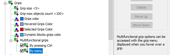
The method of access to commands to edit objects using multifunctional grips (GRIPMULTIFUNCTIONAL system variable) is selected in the section Grips > Multifunctional grips of the Options dialog box.
Objects which have multifunctional grips:
· line segment,
· arc,
· spline,
· polyline,
· hatch,
· viewport.
To edit objects with multifunctional grips:
1. Select an object.
2. Activate the multifunctional grip.
3. Press CTRL to select the editing variant.
4. Move the cursor for dynamic display of an object’s properties.
5. Click to confirm the change.
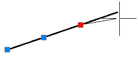
A line segment has multifunctional grips at the endpoint. Two editing modes are available:
· Normal mode: the length of the segment changes when you move the grip. In general, not only the segment length is changed, but also its orientation.
· Change of length: only the length of the segment changes when you move the grip. A new position for the endpoint is provided by the projection of the specified point along the segment’s imaginary extension. Segment orientation is not changed.
|
Normal mode |
Change of length |
|
|
|
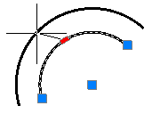
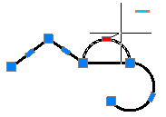
Multifunctional grips are at the endpoints and in the middle of the arc. Three editing modes are available:
· Normal mode: when you hold and move a grip on the end or middle point, the length and radius are changed:
|
|
|
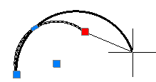
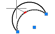
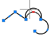
· Change of arc length: when you hold and move a grip on the end point, only the length is changed:
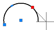
· Change of arc radius and length, when you hold and move the grip on the middle point, an arc is created similar to the source arc:
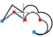
Polyline has multifunctional grips at the end of the segments and in the middle of the segments. Rotational editing modes, accessed with the CTRL button, depend on the location of the grips (end point or middle point) and segment type (linear or arc).
For improved functionality, additional symbols are displayed beside the polyline shape and near the cursor. Which symbols are shown depends on the editing mode selected:
|
|
Adds a vertex |
|
|
Deletes a vertex. |
|
|
Transforms a linear segment to an arc. |
|
|
Transforms an arc segment to linear. |


Absence of a symbol means that the normal editing mode is current - stretching by moving a segment or stretching a vertex (depends on selected grip).
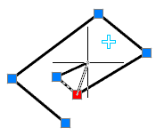
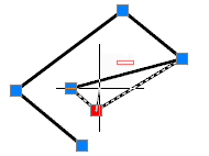
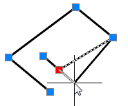
Variants of polyline editing with grips in vertexes
|
Add vertex |
Delete vertex |
Stretch with vertex |
|
|
|
|
Variants of polyline editing with grips in the middle of a linear segment:
|
Add vertex |
Transform to arc segment |
Stretch |
|
|
|
|
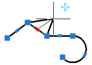
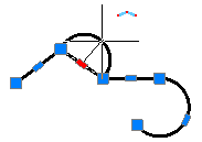
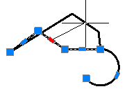
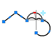
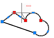
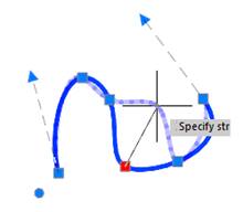
Variants of polyline editing with grips in the middle of an arc segment:
|
Add vertex |
Transform to linear segment |
Stretch |
|
|
|
|
A multifunctional mode for editing polylines can be applied to several grips located in vertexes. Two editing variants are available: normal stretching of the polyline and deleting of selected vertexes. Instead of deleted vertexes, a linear segment is drawn, even if arc segments are between the deleted vertexes.
|
Stretch vertexes |
Delete vertexes |
|
|
|
To edit several vertices of a polyline using multifunctional grips:
1. Press SHIFT.
2. Select the required grips with SHIFT pressed.
3. When you finish selecting grips, release SHIFT.
4. Select a base grip.
5. Select an editing mode with CTRL.
6. Move the cursor for dynamic display of the polyline shape.
7. Click to fix changes.
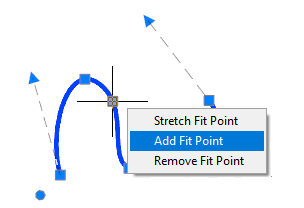
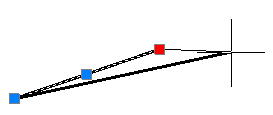
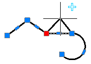
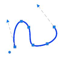
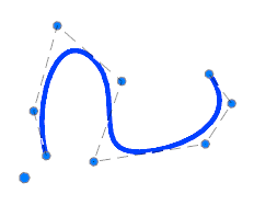
Spline has two edit modes using grips:
· Editing fit points (rectangular grips) that allows you to change the shape of a small part of a spline.
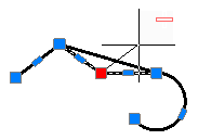
· Editing control vertices (round grips) that allows you to change the entire spline shape.
To switch between modes, click by a left mouse button on the round grip located near the spline and having a bigger diameter than the grips of control vertices.
|
Grips of fir points |
Grips of control vertices |
|
|
|
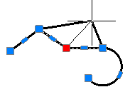
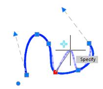
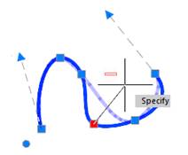
In the mode of editing fit points, multifunctional grips are available with iteration by CTRL key.
Next to the cursor, conventional icons are additionally highlighted, their appearance depends on the selected edit mode:
|
|
Adds a vertex. |
|
|
Deletes a vertex. |
The absence of a conventional icon indicates that the current mode is a common mode of grips editing – stretching by moving a segment or stretching with a vertex (depending on the selected grip).
Options for spline editing using a grip located in the vertex:
|
Add vertex |
Delete vertex |
Stretch with vertex |
|
|
|
|
To edit 3D-polylines, use multifunctional grips located in vertices.
The edit modes proposed when cycling though by CTRL key depend on the place handles are located (top or middle of a segment).
Next to the cursor, conventional icons are additionally highlighted, their appearance depends on the selected edit mode:
|
|
Adds a vertex. |
|
|
Deletes a vertex. |
The absence of a conventional icon indicates that the current mode is a common mode of grips editing – stretching by moving a segment or stretching with a vertex (depending on the selected grip).
Options for editing 3D-polyline using a grip located in the vertex:
|
Add vertex |
Delete vertex |
Stretch with vertex |
|
|
|
|
For 3D polylines multifunctional edit mode can be used for several grips located in vertices. Two editing options are available: common stretching a polyline or deleting selected vertices. A line segment is always drawn instead of deleted vertices.
|
Stretching vertices |
Deleting vertices |
|
|
|
To edit several vertices of 3D polyline using multifunctional grips:
1. Press the SHIFT key.
2. Select the required grips holding down the SHIFT key.
3. After the grip selection is completed, release the SHIFT key.
4. Select the base grip.
5. Select the edit mode by the CTRL key.
6. Move the cursor for dynamic display of the change of polyline change.
7. Left-click to fix the changes.
Editing Viewports in Paper Space
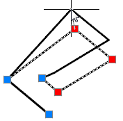
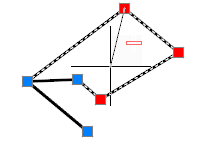
You can edit any viewports in paper space using multifunctional grips where closed polylines and splines are used as boundaries. The process of editing the boundaries of the viewport is the same as editing of a spline or polyline with multifunctional grips.
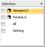
As viewports consist of two objects (viewport and display border), to edit them in the Selection dialog box select a polyline or spline, not a viewport:
If display of the Selection dialog box is switched off, select a polyline or spline in the Properties panel in the Object type field:
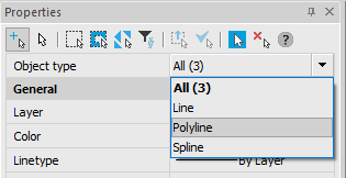
Select a viewport with a window or crossing window, if you select with the pickbox in the Object type field in the Properties panel, Viewport is displayed by default.
In nanoCAD, using multifunctional grips you can edit the shape of:
· associative hatches, which use closed polylines and splines as linked contours;
· non-associative hatches.
Changing the shape of an associative hatch using multifunctional grips and a linked contour does not differ from the editing of a polyline or spline using multifunctional grips.
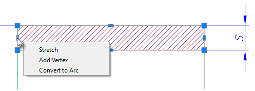
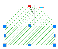
If you select non-associative hatch, the same multifunctional grips are displayed as in a polyline, except the round grips are used to move the hatch:
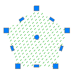
The process of editing a non-associative hatch shape is the same as editing of a polyline with multifunctional grips.
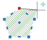
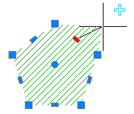
Variants of non-associative hatch shape editing with grips in a boundary vertex:
|
Add boundary vertex |
Delet boundary vertex |
Stretch boundary by top |
|
|
|
|
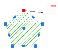
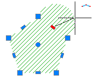
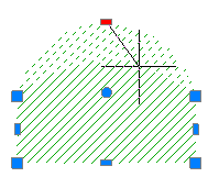
Variants of non-associative hatch shape editing with a grip in the middle of a boundary linear segment:
|
Add boundary vertex |
Transform linear segment of boundary into arc segment |
Stretch |
|
|
|
|
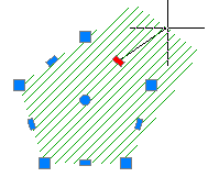
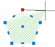
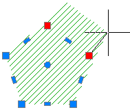
Variants of non-associative hatch shape editing with a grip in the middle of a boundary arc segment:
|
Add boundary vertex |
Transform arc segment of boundary into linear segment |
Stretch |
|
|
|
|
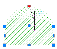
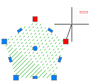
For non-associative hatch, a multifunctional editing mode can be applied to several grips located in the boundary vertexes. Two variants of editing are available: normal stretching of boundary and deleting of selected vertexes. Instead of deleted vertexes a linear segment is drawn, even if arc segments were between deleted vertexes.
|
Stretch boundary vertexes |
Delet boundary vertexes |
|
|
|
To edit several vertexes of non-associative hatch area using multifunctional grips:
1. Press SHIFT.
2. Select the required grips with SHIFT pressed.
3. When you have selected the grips, release SHIFT.
4. Select a base grip.
5. Select an editing mode with CTRL.
6. Move the cursor for dynamic display of the hatch shape.
7. Click to fix changes.