

-
-
-
-
-
-
-
-
-
-
-
-
-
Snap and Grid Mode
-
-
-
-
-
-
-
-
-
-
-
-
-
-
-
-
-
-
-
-
-
-
-
-
-
-
-
-
-
-
-
-
-
-
-
-
Snap and Grid Mode
 Menu: Tools –
  Drafting settings… > Snap and Grid tab
Status bar:  and
and 
 Hotkeys: F9 and F7
 Command line: DDRMODES, DSETTINGS, SE
Grid is an ordered sequence of points, which with SNAP mode allows specifying restrictions of the cursor movement to define accurate coordinates. You can switch the grid on/off at any time when you are working with a drawing. Changing grid spacing does not affect any drawing objects.
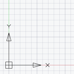
When the grid is on, the positive directions of the abscissa and ordinate axes are displayed in color, which additionally helps navigate the editing plane. The colored rays are directed from the origin of coordinates. Red is assigned to the X-axis, green is assigned to the Y-axis.
Grid is not printable.
If SNAP mode is switched on, the cursor jumps from node to node with the specified snap spacing. Snap spacing and grid spacing can be different but very often their values are the same. Grid can have high spacing and snap spacing can be small to give a user the capability to specify points of high precision. For example, you can set grid spacing to 10 units, and snap spacing to 1 unit. Grid and snap spacing can be different along the X and Y axes.
Major line – additional lines are also highlighted:
Adaptive grid – grid display depends on the drawing scale. When zooming in, additional grid lines appear; when zooming out, they disappear. The frequency of these lines is determined by the frequency of the main grid lines.
A grid showing drawing limits, allows visualization of the drawing dimensions to place base elements on the initial stages.
The parameters of the SNAP and GRID modes are specified in the Snap and Grid tab of the Drafting settings dialog box or in the context menus.
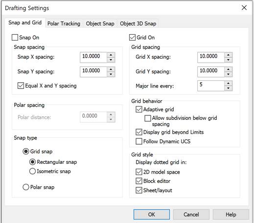
Tab parameters:
|
Snap On (F9) |
Switches snap mode on/off. Grid snap mode can also be turned on/off by the |
 button in the status bar,
 Snap spacing
|
Snap X spacing: |
Specifies the X spacing. The value should be a positive real number. (SNAPUNIT system variable). |
|
Snap Y spacing: |
Specifies the Y spacing. The value should be a positive real number. (SNAPUNIT system variable). |
|
Equal X and Y spacing |
Sets equal spacing between X and Y. Snap spacing may differ from grid spacing. |
Polar snap
|
|
|
|
spacing: |
Specifies a snap when setting the polar snap mode (POLARDIST system variable). When set to zero, a polar snap spacing is equal to snap spacing by X. A polar snap only works when polar and/or object tracking is enabled.. |
|
|
|
|
|
|
Snap type
|
Grid snap |
Specifies a grid snap for the cursor movement to horizontal and vertical grid points (SNAPTYPE system variable). |
|
Rectangular |
Specifies the standard mode for rectangular snap. In case of grid and rectangular snap type, the cursor moves along the rectangular structure nodes. (SNAPSTYL system variable). |
|
Isometric |
Specifies the mode of isometric snap and activates the isometric drafting mode. In case of grid and isometric snap type, the cursor moves along the isometric grid nodes. (SNAPSTYL system variable). |
|
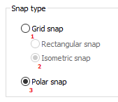
Polar |
Specifies the polar snap. With polar snap and enabled polar tracking, the cursor can move along imaginary lines drawn from the tracking base point at the angles specified on the Tracking tab. (SNAPTYPE system variable). To use the polar snap in the isometric drafting mode, you should first set the isometric snap, and then switch to polar snap:
|
Grid:
|
Grid on (F7) |
Enables/Disables the display of grid on the screen. The grid mode can also be turned on/off using |
 button in the status bar,
 Grid spacing
|
Snap X spacing: |
Specifies the distance between grip nodes by X axis. When set to zero, a grip spacing is equal to a grip snap (GRIDUNIT system variable). |
|
Snap Y spacing: |
Specifies the distance between grip nodes by Y axis. When set to zero, a grip spacing is equal to a grip snap (GRIDUNIT system variable). |
|
Major line every: |
Specifies the number of grip nodes through which the main (thickened) grip lines are displayed (GRIDMAJOR system variable). |
Grid behavior
|
Adaptive grid |
Switches adaptive grid mode on/off. |
|
Allow subdivision below grid spacing |
Switches division of the grid spacing on/off. |
|
Display grid beyond limits |
Switches display of the grid beyond specified limits on/off. |
|
Follow Dynamic UCS |
Sets the grid plane in accordance with XY plane of dynamic UCS (GRIDDISPLAY system variable). |
Grid style. Dotted grid display area:
|
2D model space |
Enables/disables display of the grid as dots in 2D model space (system variable GRIDSTYLE = 1). |
|
Block editor |
Enables/disables display of the grid as dots in the block editor (system variable GRIDSTYLE = 2). |
|
Sheet/layout |
Enables/disables display of the grid as dots in layouts and paper space layouts (system variable GRIDSTYLE = 4). |
Default system variable GRIDSTYLE = 0 - Grid is dispolayed as lines in model space, block editor, layouts and paper space sheet sets.
The context menu of the SNAP button:
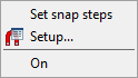
Parameters:
|
Set snap steps |
Specifies the X and Y spacings in the command line (SNAPUNIT variable). |
|
Setup… |
Opens the Drafting settings dialog box. |
|
On |
Switches snap mode on/off. |
The context menu of the GRID button:
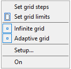
Parameters:
|
Set grid steps |
Specifies the X and Y spacing in the command line. |
|
Set grid limits |
Specifies the limits of the grid display. |
|
Infinite grid |
Switches off restrictions for the grid display. |
|
Adaptive grid |
Switches adaptive grid mode on/off. |
|
Setup… |
Opens the Drafting settings dialog box. |
|
On |
Switches display of the grid on/off. |