

-
-
-
-
-
-
-
-
-
-
-
-
-
-
3D-Navigation View Modes
-
-
-
-
-
-
-
-
-
-
-
-
-
-
-
-
-
-
-
-
-
-
-
-
-
-
-
-
-
-
-
-
-
-
3D-Navigation View Modes
 Ribbon: View – Navigate >
  Perspective View
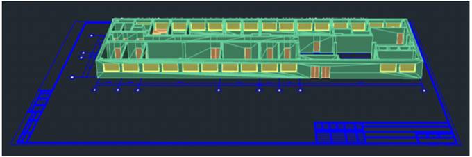
Ribbon: Point clouds – Navigate > Prospective View
Toolbar: Views and projections –
 Command line: FITPERSPECTIVEVIEW
Displays 3D-model in the perspective projection mode. When using 3D Walk and 3D Fly commands the mode starts automatically.
Ribbon: View – Navigate >  Orthogonal View
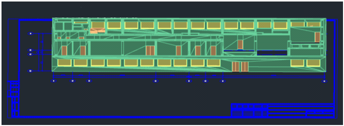
Ribbon: Point clouds – Navigate > Orthogonal View
Toolbar: Views and projections –
Command line: FITORTOGONALVIEW
Displays 3D model in orthogonal projection mode.
Differences in Zooming in 3D-Projections
The result of scrolling the mouse wheel in a perspective projection differs from the work in a parallel one. While in a parallel projection the scale of display changes, which results in visual extension or compression of the visible area (analogue of Zoom+/- command), then in the perspective projection the viewpoint moves farther or closer from/to the nearest visible object, which is the analogue of Fly command (3DFLY).
Thus, scrolling the mouse wheel in a perspective projection allows you to “go through” all visible objects, in contrast to a parallel projection, where the same action will only lead to the change of display scale, i.e. visual “stretching” of the visual area.
In addition, the step of changing the display scale in a parallel projection, as well as the step of moving the camera in a perspective projection is calculated adaptively depending on the distance to the object under cursor, so that zooming/approaching to remote objects is faster, with adaptive step reduction while approaching. In case if the cursor projection along the camera line does not fall on any object, i.e. the cursor is “in emptiness”, the default step value is used, as it was in the previous version.