

-
-
-
-
-
-
-
-
-
-
-
-
-
-
-
-
-
-
-
-
-
-
-
-
-
-
-
-
-
-
-
-
-
-
-
-
-
Plot
-
-
-
-
-
-
-
-
-
-
Plot
 Ribbon: Output – Plot >
  Plot
Plot
Menu: File –  Plot…
Plot…
Toolbar: Main –
 Hot keys: CTRL+P
Command line: DWFOUT, PLOT
The command opens the Plot dialog box that differs from the Page Setup dialog box only in one section – Page setup – and the Plot button instead of OK button, as well as possibility to set the number of copies to be plotted:
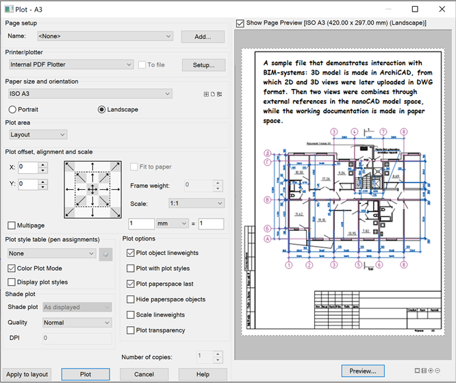
If there is no plotting device (plotter/pc3) specified in the document, the Internal PDF Plotter will be used. In this case, whenever possible, the format dimensions and orientation specified in the pc3 file or document are preserved. The Internal PDF Plotter will select the format that exactly matches the size specified in the document or pc3, or the next larger one from the list of formats available for that plotter. The list of available formats is configured in the Options dialog and in the Paper Format List Editor.
Options:
Page setup
|
|
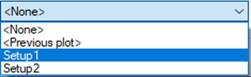
Drop-down list that displays the page setups available in the document. After the first document plot the <Previous Plot> option becomes available in the list; it stores the settings of the last plot set. |
|
|
Button to open the New Plot Set dialog box to specify the name for a new page setup and add it to the document’s page setups. |

|
Number of copies: |
Sets the number of copies to be plotted. |
Description of other options – see “Page Setup” section.
|
|
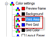
When setting the plot area in the layout space, the screen displays: · size and orientation of the paper format selected to plot as a frame displayed by a solid blue line; · real plot area for the specified printer and selected paper format as a frame displayed by a dashed blue line; · specified plot area of the document as a frame displayed by a dashed red line. The frame colors specified by default can be changed in the Color settings section of the Options dialog box (the Tools menu – Options): |
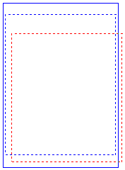
note: When specifying plot areas in the model space, the screen displays only the specified plot area as a frame displayed by a dashed red line.
To set several plot areas:
1. In the drop-down list of the Plot area section, select the Window option.
2. After closing the dialog box, specify the first plot area on the screen by setting two opposite rectangle corners.
3. In the newly opened Plot dialog box click  Add window print area button and specify the second plot area.
4. Repeat the process of specifying for other plot areas.
5. To cancel the last specified plot area, click the  Delete last print area button. At repeated clicking this button, the previous plot area will be deleted and so on.
attention! When clicking the Delete last print area button, the Plot dialog box is not closed.
note: To cancel all specified plot areas and specify a new plot area, click the New window print area button.
note: It is recommended to specify the plot areas of the same format. If, for example, select A4 Portrait paper size and specify several plot areas of A4 format, and then select A3 Landscape paper size and additionally set several plot areas of A3 format, then all specified areas (including A4) will be printed on the A3 Landscape paper.
For multipage plot:
1. Select a printer.
2. Specify the paper size and orientation.
3. Turn off the Fit to paper option, if it is on.
4. Specify the plot scale.
5. Turn on the Multipage option.
6. Specify the plot area.
7. If necessary, set the plot area offset or turn on the Center the plot option.
The normal preview window displays the page selected for preview, its number and total number of pages the selected plot area was paginated (Page 1/15):
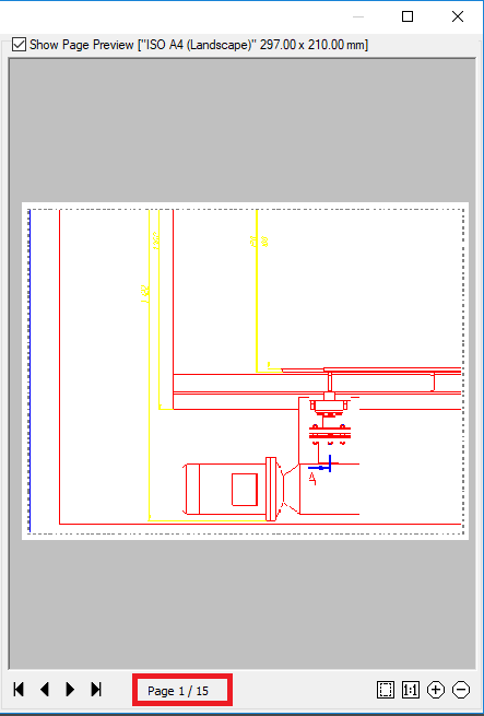
The multipage plot is useful to print large formats (A0, A1, etc.) on printers that do not support a plot of these formats.