

-
-
-
-
-
-
-
-
-
-
-
-
-
-
-
-
-
-
-
-
-
-
-
-
-
-
-
-
-
-
-
-
-
Tables
-
-
-
-
-
-
-
-
-
-
-
-
-
-
-
-
-
-
-
-
-
-
-
Tables
 Ribbon: Annotate – Tables –
  nanoCAD Tables
Menu: Draw – Tables >  Tables…
 Toolbar: Draw –
 Command line: TABLE, TB
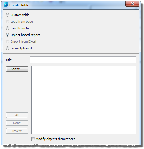
The command opens the Create table dialog box:
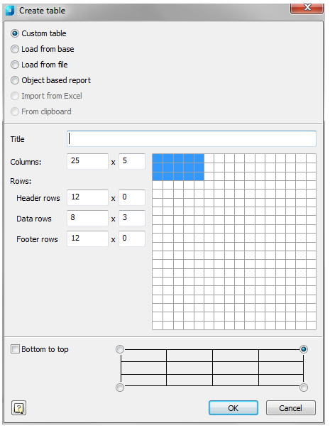
To create a non-standard table:
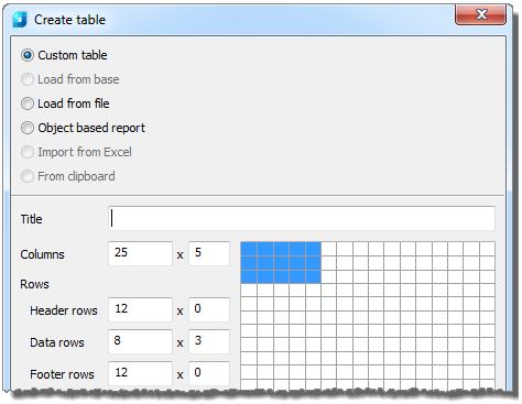
1. Click the Custom table item.
2. Use the numeric entry fields to set the parameters for the custom table. The number of rows or columns and cell sizes can be altered later when the table is first edited.
To insert a standard table:
1. Click the Load from base item.
2. A standard table can be inserted from the nanoCAD library:
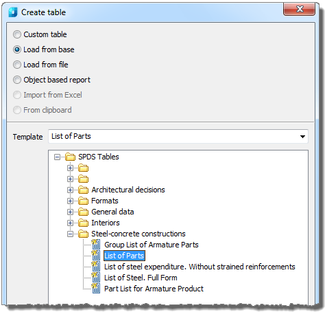
3. Choose the desired table type in the dialog box. All basic standard tables are present in the nanoCAD library.
To insert a table from a file:
1. Click the Load from file item.
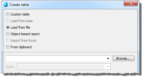
2. Click the Browse button and select the table file.
Supported formats:
· tbl - tables format;
· dat - data file or text file;
· mdb - Microsoft Access database;
· xls - Microsoft Office Excel table;
· xlsx - Microsoft Office Excel 2007 table;
· csv - table, cells are divided by commas;
· txt - standard text file;
· xml - XML document.
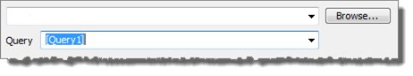
When loading the table from an mdb file, the list of base queries is displayed in the drop-down list:
When loading the table from xlsx or xls files, it is necessary to select the list in the Excel document:
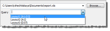
It is important! The list choice can be carried out after loading the table from a file.
Accomplish this:
1. In the Source query line, enter the required list from the document.
note: In the table properties, the Source file line displays the path to the initial table file.
2. Then in the Table edit dialog box click the Update table from external source  icon.
icon.
note! To import tables from files, it is possible to drag a file from the browser to the Table edit dialog box.
When dragging a file from the browser into the table field, the imported table is added to the existing table.
When dragging a file from the browser into the dialog box field, the imported table replaces the existing table
To generate an object base report:
1. Click the Object based report item.
2. To choose the required objects, click the Select button:
3. Setting of search conditions is carried out in the Quick Selection dialog box:
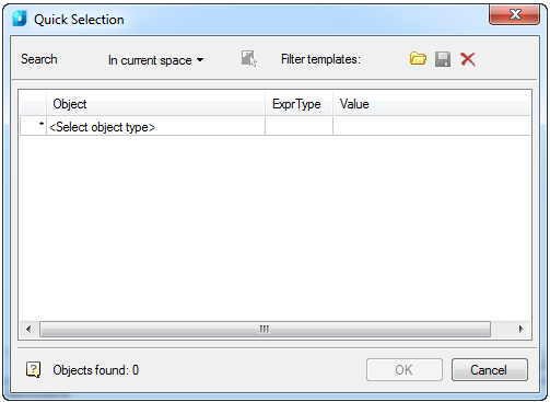
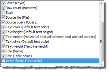
4. Which attributes of the chosen objects the report is based on are also set in this dialog box.
The attributes to be included in the report are switched by tags in the list or switches:
Buttons:
|
|
All attributes are selected. |
|
|
The choice is removed from all attributes. |
|
|
Selection of attributes is inverted. |


The report with a template of a view is created in the table:
=Iff(Exist(Object."AttributeName");Object."AttributeName";"")
This expression checks the existence of the given attribute line with the AttributeName name and uses its value in the cell. Otherwise, it leaves a cell empty:
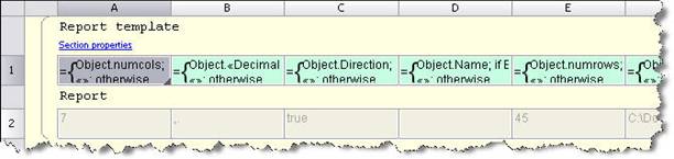
The number of columns in the table is defined by the number of chosen attributes.
Note: If the objects group was previously selected on the drawing and the Tables  command is activated, then you will be offered the option to create an object-based report.
To import table from Excel:
1. Select the Import from Excel item.
Note! The document should be opened to make this item active.
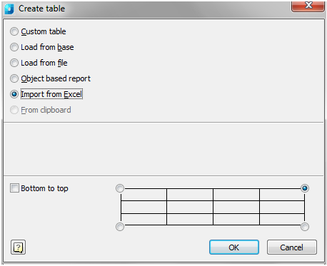
2. Choose the location of the base point:
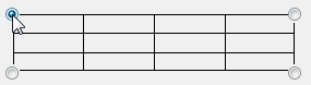
3. Choose the row numbering method:

If the Bottom to top box is checked, the rows will be numbered in reverse order.
4. Click the OK button and pick the insertion point in the drawing.