

-
-
-
-
-
-
-
-
-
-
User Coordinate System
-
-
-
-
-
-
-
-
-
-
-
-
-
-
-
-
-
-
-
-
-
-
-
-
-
-
-
-
-
-
-
-
-
-
-
-
User Coordinate System
nanoCAD uses two kind of coordinate systems: world coordinate system and user coordinate system.
Only one coordinate system is active at any time; it is called current.
World coordinate system is a base coordinate system and cannot be redefined (X axis is set horizontally, Y axis vertically and Z is perpendicular to XY plane). The main difference of the world coordinate system from the user coordinate system is its rigidity and that it can be the only one (for every model space and layout).
The usage of the user coordinate system has almost no restrictions; it can be placed at any point of the space and with any angle to the world coordinate system. UCS can be moved and rotated to specify points on the three dimensional and rotated views. Node points and base directions, defined by the SNAP, GRID and ORTHO modes are rotated with UCS.
Commands for changing the UCS position set a new coordinate system, the so-called current coordinate system.
Thecurrent coordinate system inherits the parameters of the previous coordinate system, only the required values are changed.
 Ribbon: View – Coordinates >
  World UCS
Menu: Tools – Coordinate system > World UCS
 Toolbar: UCS –
The command sets the parameters of the world coordinate system for the current user coordinate system.
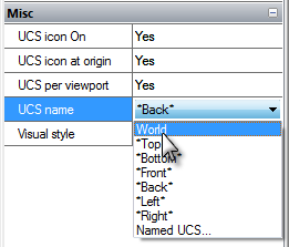
To set a World coordinate system quickly:
1. Click in the UCS name field on the Properties panel.
2. Open the drop-down list and select World:
Changing the UCS Position from the Command Line
 Command line: UCS
Command options:
|
Face |
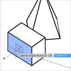
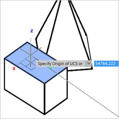
Sets the UCS in the plane of the face of a 3D object (submesh, polyface mesh, polygonal mesh, 3D-solid, parameteric solid).
Hover over the desired face to see how the UCS will be aligned. The Dynamic UCS (F6) mode must be active. The face is highlighted, and an icon is displayed near the cursor, previewing the direction of the UCS axes. The origin point will be placed at the center of the cursor in the plane of the selected face.
The direction of axes of the new UCS depends on the edge that the cursor crossed when hovering over the face. So the X axis is set parallel to the intersected edge in the direction from the initial vertex of the intersected edge. The Y axis is perpendicular to the X axis and directed towards the inside of the face. The Z axis is so that a right-handed coordinate system is obtained. When you hover the cursor over the same face from the side of another edge, the orientation of the UCS axes also changes.
|
|
Named |
Saves and restores frequently used UCS orientations by name. The option starts the following prompt in the command line: Enter an option [Restore/Save/Delete/?] Options: Restore - Replaces the current UCS with a new from the list of named UCS. Save - Saves the current UCS with the specified name. Delete - Deletes UCS from the list of named UCS. ? - Shows a list of named UCS. |
|
Restore |
Replaces the current UCS with one from the list of named UCSs. |
|
Save |
Saves the current UCS with a specified name. |
|
Delete |
Deletes the UCS from the list of named UCS. When deleting and restoring, named UCS can be selected in the command line: Enter UCS name to delete <none>: or [?/UCS1/UCS2/UCS]: |
|
? |
Shows the list of named UCS. |
|
Object |
Sets the origin and the direction of the UCS axes according to the geometry of the existing object. |
|
View |
Specifies a new coordinate system within the XY plane, set perpendicular to the direction of sight and parallel to the viewport’s plane. The position of the origin is not changed. The X axis is set horizontally and the Y axis is set vertically. |
|
World |
Matches the current UCS to the World coordinate system (restores the World coordinate system). |
|
X/Y/Z |
Rotates the current UCS around the selected axis. |
|
ZAxis |
Specifies the UCS using the positive direction of the Z axis: the origin is placed at the first specified point; the positive direction of the Z axis is set through the second specified point. |
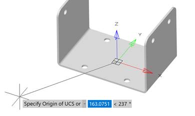
Command prompts:
|
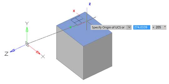
Specify origin of UCS or [Named/Object/View/World/X/Y/Z/ZAxis] <World>: |
Select start point of UCS. |
|
Specify point on X-axis or <Accept>: |
Specify a point on the positive ray of the X axis. |
|
Specify point on XY plane or <Accept>: |
Specify a point on the positive ray of the Y axis in the XY plane. |