

Tuning Program Parameters
 nanoCAD Button:
  Options…
 Ribbon: Manage – Customization –
  Options…
Menu: Tools – Options…
 Hotkeys: CTRL+9
Command line: OPTIONS, PREF
You can launch the command from the context (right-button) menu of the command line:
Tuning program parameters is performed in the Options dialog box:
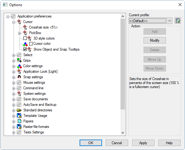
There is a tree of options, grouped by sections, in the left part of the dialog box.
To see the parameters of the group, click twice on the name of the section or select the  icon to the left of the section name. If you click the
  icon, the section (subsection) will be closed.
The Add, Modify and Delete buttons of the Action section become available; this means that the selected parameter from the tree can be edited.
|
|
Adds new option to the selected subfolder. |
|
|
Modifies the selected option. |
|
|
Deletes the selected option. |
|
|
Moves the selected option up. |
|
|
Moves the selected option down. |
|
|
Applies changes without closing dialog. |


The lower right field of the dialog displays brief information about the selected section, subsection or parameter.
To change a value of a parameter:
· Select/deselect the checkbox to the left of the parameter
or
· Click twice on the parameter
or
· Select the parameter and select the Modify button.
 The section of graphic cursor setting.
|
|
Crosshair size<5%> |
Sets the size of the crosshair as a percentage of the display size. |
|
|
Pickbox |
The pickbox size. |
|
|
PickBox size <4> |
pickbox size in pixels. |
|
|
3D style colors |
3D color style for the crosshair and pickbox. |
|
|
Cursor color |
Cursor color. The default is white. When assigning a cursor color in grayscale, the cursor display in the graphic area of the drawing is inversely adjusted to the background color (on light it becomes dark, on dark it becomes light). A Grayscale color has the same RGB components, for example For any other combinations of RGB components, the cursor color will be displayed according to the user-specified parameters. If the Use default color option is selected in the Category Name and Color window, the specified cursor color will be ignored ( |
|
|
Show Object and Snap Tooltips |
Switches object tooltips on/off. |


 Red = 127, Green = 127, Blue = 127. White (RGB 255, 255, 255) and black (RGB 0, 0, 0) colors are included in this color mode.
 ), the cursor color will inversely adjust to the background color, including colored
 Parameters of frames to select objects.
|
|
Color frame |
Color frame. |
|
|
Color fence |
Color fence. |
|
|
Transparency <70> |
Transparency of frame and fence. |
|
|
Object limits for Inspector palette <25000> |
Limits the number of objects that can be changed at one time in the Properties functional bar. Value can be changed from 0 to 32767. 0 – switch of the limit edited objects, but this can decrease performance in large drawings. The limit doesn’t affect to General section in Properties functional bar). |
|
|
Window selection method |
Defines the method of objects selection in a drawing. |
|
|
Click and Click |
Specifies two points of selection fence or frame by two clicks. |
|
|
Press and drag |
Press left mouse button and drag the cursor to stretch selection frame. Then release the mouse button. |
|
|
Both – Automatic detection |
The method is chosen automatically by the program. |
|
|
Lasso selection |
Enables/Disables the lasso selection method. |
|
|
Keep pre-selection after modification |
On/Off keep pre-selection after modify commands: Move, Rotate and Scale. When this mode is enabled, the selection set includes: objects modified or created as a result of the Move, Rotate, Scale, Mirror, or Copy command, as well as selected source objects and objects created as a result of the Array command. Cancel the selection of objects by pressing the ESC key. |
|
|
Selection preview |
Selections preview settings. |
|
|
Selection preview max objects count <100> |
Max count of selected objects in preview. The zero value disables preview. |


Objects highlight style.
|
|
Selected objects |
How to highlight objects in selection set. |
|
|
Line highlight style |
How to highlight edges and linear parts of objects. |
|
|
Object highlighting the dotted lines |
Use dotted lines to highlight lines. |
|
|
Color and transparency |
Highlight lines using color and transparency. |
|
|
Face highlight style |
How to highlight faces. |
|
|
Object highlighting by pattern |
Highlight faces using object texture. |
|
|
Color and transparency |
Highlight faces using color and transparency. |
|
|
Selection preview |
How to highlight objects in selection preview. |
|
|
Line highlight style |
How to highlight edges and linear parts of objects. |
|
|
Object highlighting |
Highlight lines using object highlighting. |
|
|
Color and transparency |
Highlight lines using color and transparency. |
|
|
Face highlight style |
How to highlight faces. |
|
|
Object highlighting by pattern |
Highlight faces using object texture. |
|
|
Color and transparency |
Highlight faces using color and transparency. |


Objects fading level.
|
|
Xref display |
Controls the dimming for all Xref-objects in a drawing. (XDWGFADE system variable). |
|
|
In-place edit and annotative representations |
Specifies the fading intensity value for drawing objects during in-place reference or block editing (XFADECTL system variable). |
|
|
Locked layers |
Controls the amount of fading for objects on locked layers. (LAYLOCKFADECTL system variable). |
 Parameters of the grips of the selected objects.
|
|
Grip size <5> |
Grip size in pixels. |
|
|
Grip max objects count <100> |
The maximum number of selected objects that can still display grips. Grips will not be displayed if the number of selected objects is greater than the specified value. |
|
|
Grips color |
Grips color. |
|
|
Hovered grips color |
Grips color under cursor. |
|
|
Selected grips color |
Selected grips color. |
|
|
Dynamic block grips color |
Color of grips of dynamic blocks. |
|
|
Multifunctional grips |
Controls the way to access object editing commands using multifunction grips (GRIPMULTIFUNCTIONAL variable). |
|
|
By pressing Ctrl |
The parameters of multifunction grips become available when the CTRL key is pressed repeatedly. |
|
|
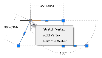
By menu |
A pop-up menu with options for multifunction grips appears, when cursor is placed at an object grip.
|


 Colors of the program components.
|
|
Model space Color |
The color of background in model space. |
|
|
Paper space Color |
The color of layout in paper space. |
|
|
Layout Background Color |
The color of background in paper space. |
|
|
Grid Color |
The color of Grid points. |
|
|
Print Area Color |
The frame color that indicates a print area. |
|
|
Print Margins Color |
The frame color that indicates the paper format edges. |
|
|
Block Editor Background |
Block Editor background color. |
|
|
Orbit Center |
The color of Center mark for Virtual Trackball command. |
|
|
Pan Center |
The color of Center mark for Pan command in PERSPECTIVE=1 mode. |
|
|
Dimensional constraints |
The color of dimensional constraints. |
|
|
Dimension lines |
Set color for dimension lines (DYNCONSTRAINTSCOLOR system variable) |
|
|
Dimension texts |
Set color for dimension texts (DYNCONSTRAINTSTXTCOLOR system variable) |


Select one of predefined visual styles:
· Windows default
· Aqua
· Blue Laguna
· Deep Ice
· Graphite
· Iceberg
· Light
· Obsidian Black
· Platinum
· Silver
· Steel
NOTE: You can use Apply button for fast preview of the selected visual.
 Defines the Snap settings.
|
|
Hold Aperture Size <10> |
The size of a cursor frame in snap mode. |
|
|
Show Aperture Box |
Switches the aperture box on/off in the snap mode. |
|
|
Snap Marker size <5> |
Snap marker size. |
|
|
Show Tooltips |
Turns on the display of a snap name. |
|
|
Vector Marker Color |
The color of the snap marker when snapping to a vector object. |
|
|
Otrack marker color |
Sets color of object snap tracking marker in snap to vector object. |
|
|
Rays color |
Sets color of rays in snap to vector object. |
|
|
Snap for Objects |
Sets snap for different objects. |
|
|
Snap for Dimensions |
Indicates whether the dimensions considered in the calculation of the intersection points. |
|
|
Snap for Layouts |
Indicates whether the layout borders considered in the calculation of the intersection points. |
|
|
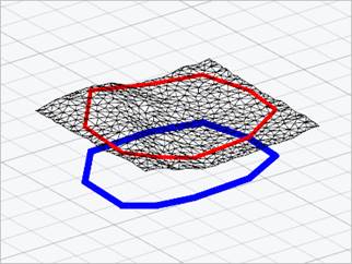
Replace Z value with Current Elevation |
Controls the value of Z coordinate in an object snap. When the option is disabled, the value of Z coordinate of the specified point is used. When the option is enabled, the value of Z coordinate is replaced by the value of its projection to XY plane of the current UCS or, if non-zero value is set for the ELEVATION variable, on the plane parallel to XY plane on the preset level. The option is synchronized with the OSNAPZ variable. Below there are two 3D polylines created with a snap to mesh vertices. Red – in a common snap mode, blue – when the option of Z-coordinate replacement is enabled:
|


Manages mouse input, dimension input, dynamic tooltips, and tooltip appearance.
|
|
Pointer input on |
Enables mouse input. |
|
|
Dimensional input on |
Enables dimensions input. |
|
|
Pointer input options |
Set tooltips parameters for mouse input. |
|
|
Polar or Cartesian input format |
Manages the display of tooltips in polar or Cartesian coordinate formats. |
|
|
Use polar format |
Displays tooltips in polar coordinate format. |
|
|
Use cartesian format |
Displays tooltips in Cartesian format. |
|
|
Relative or Absolute input format |
Manages the display of tooltips in relative or absolute coordinate formats. |
|
|
Use relative format |
Displays tooltips in relative coordinate format. |
|
|
Use absolute format |
Displays tooltips in absolute coordinate format. |
|
|
Show prompt |
Enables/Disables the display of dynamic input prompts. |
|
|
Tooltip color |
Sets the tooltip color. |
|
|
Tooltip transparency <0%> |
Sets the tooltips transparency. |

3D Orbit and Free Orbit Settings
|
|
Horizon lock |
If the setting is enabled, then when the model is rotated, the projection of the Z axis remains vertical in the screen plane. When disabled, model rotation is not limited. Controlled by the VIEWHORIZON system variable. |
|
|
3D Orbit moujse sensitivity <300>% |
Rotation speed adjustment. The minimum rotation speed is 25%, the maximum is 400% of the nominal value. The default is 300%. |
|
|
Rotate the model with the mouse wheel |
If the setting is enabled, then pressing the mouse wheel (or the combination of SHIFT + mouse wheel) will be used to launch the 3D Orbit command in transparent mode. If the setting is disabled, then pressing the mouse wheel (including in combination with SHIFT) will not launch the 3D Orbit command. Only panning will be performed. |
|
|
Rotate model: |
Section for specifying the model rotation method. |
|
|
SHIFT+mouse wheel |
Mouse wheel click to pan. Enables/disables rotation of 3D orbit when using SHIFT+mouse wheel (starts the 3D Orbit command in transparent mode). |
|
|
Mouse wheel |
By pressing the mouse wheel, the model is rotated (the 3D Orbit command is launched in transparent mode). While the combination of SHIFT + mouse wheel performs panning. |
|
|
Orbit center |
Locates rotation center of 3D Orbit and Free Orbit. |
|
|
Visible objects |
Places rotation center to the center of objects you’re viewing. |
|
|
Visible parts of objects |
Places rotation center to the center of objects parts you’re viewing. |
|
|
Mouse Wheel scale factor <1.5> |
Scale factor used to scale with the Mouse Wheel. If scale factor is more than 1 - forward scrolling increase the scale, if less than 1 – decrease. If 1 – scaling using mouse wheel is disabled. |
The section redefines functions of the right button.
|
|
Default Mode: |
This section defines the behavior of the right mouse button in normal mode, when there are no objects selected and no running commands. |
|
|
Repeat last command |
Disables the standard right-click context menu. Simulates pressing the ENTER key, which causes the last command to run again. |
|
|
Shows Popup Menu |
Displays the standard context menu. |
|
|
Edit Mode: |
This section defines the behavior of the right mouse button in edit mode when objects are selected but there are no running commands. |
|
|
Repeat last command |
Disables the right-click context menu. Simulates pressing the ENTER key, which causes the last command to run again. |
|
|
Shows Popup menu |
Displays the context menu for editing selected objects. |
|
|
Command mode: |
This section defines the behavior of the right mouse button when it is pressed during a running command. |
|
|
Sends “ENTER” |
Disables the right-click context menu. Simulates pressing the ENTER key. |
|
|
Shows Popup menu |
Displays the context menu of the running command. |
|
|
Shows Popup menu when command options present |
Calls the context menu of a command only if there are available options in the command line. If there are no options in the command line, pressing the right mouse button corresponds to pressing ENTER. |
|
|
Shows Popup menu after delay |
Enables the mode which considers the duration of right button holding: short click – repetition of command or simulating pressing the ENTER key, according to the mode, long hold – opens the context menu. |
|
|
Delay <250> ms |
Specifies in milliseconds, the duration of right button holding to open the context menu. By default, the value is 250 ms. |
|
|
Always show Popup menu when objects selected |
If enabled, then if there is one or more objects in the selection, pressing the right mouse button always brings up the context menu, regardless of the duration of the press. |
|
|
Scroll screen pages <3> |
A document Scrollbar movement range. |
Section to configure interface of the floating document window.
|
|
Ribbon and menu bar |
Whether a document floating window should contain the ribbon and menu bar. |
|
|
Status bar |
Whether a document floating window should contain the status bar. |
The section sets the parameters of the command line.
|
|
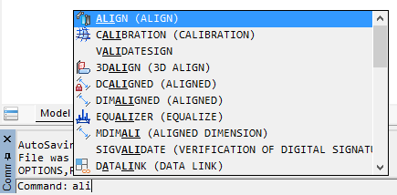
Use Autocomplete |
Switches on/off the auto complete mode, when after entering one or several first letters of the command, the command is auto completed in the command line. |
|
|
Autoselect mode |
Advanced options of autocomplete. |
|
|
Don’t select |
Manual selection. |
|
|
Select on prefix |
When fuzzy complete disable: first item will be selected only if it has common prefix with command line. When fuzzy complete enable: item will be selected if it has common characters with command line. For example, zll selects ZoomAll command. |
|
|
Always select |
First item will be selected always. |
|
|
Completion content |
Autocompletion list content. |
|
|
Complete system variables |
Shows system variables in autocompletion list. |
|
|
Complete blocks |
Shows block names in autocompletion list. |
|
|
Complete tools |
Shows commands from Tool Palette in autocompletion list. |
|
|
Additional options |
Additional options of autocomplete. |
|
|
Autocomplete during delay |
Selection of the most probable command before autocomplete list is. |
|
|
Completion list delay: <0.3> s |
Amount of time that elapses before completion list is shown.
|
|
|
Fuzzy complete |
Automatic correction of errors while typing. |
|
|
Command line background color |
Sets the background color of the command line. |
|
|
Command line text color |
Sets the text color of the command line. |
|
|
Use alternate font |
Switches on/off the using of alternative font in the command line. |
|
|
Font Height <12> |
Specifies font height in the command line. |

Video subsystem and graphic displaying settings.
|
|
Vectorizer Type |
Specifies graphic hardware acceleration library to use by program. This setting will be applied after restart of the nanoCAD. |
|
|
OpenGL |
Use OpenGL |
|
|
DirectX |
Use DirectX By default, when you select DirectX, DirectX 11 is activated. If it is not supported (for example, when working via RDP), then DirectX 9 is activated. You can manually change the DirectX version using the DirectX enhanced compatibility mode option or the NCGS_TOGGLE_DIRECTX command. |
|
|
Use anti-aliasing |
Enables/Disables the jagged smoothing effect when displaying drawing graphics (antialiasing). Smoother line displaying. Setting will be applied for new opened or created document. This effect does not work when enhanced compatibility mode is enabled. |
|
|
Rendering optimization |
Rendering optimization settings. |
|
|
Optimize rendering objects with linewidth |
Disables linewidth in navigation mode – Zoom, Pan, etc. |
|
|
Optimize small details rendering |
Disables points and other graphic with the same size in navigation mode – Zoom, Pan, etc. |
|
|
Simplify text less than <2> pixels |
All text smaller than specified value will be shown in a drawing as empty bounding boxes. Regeneration is required. |
|
|
Min mipmap level size <512> pixels |
Specifies a minimum level of detail to speed up work with large raster images. Affects on raster mipmap pyramid generation. Defines smallest raster mipmap level in pixels. |
|
|
OpenGL settings |
OpenGL settings. |
|
|
Screen caching |
Settings for the automatic and manual setup of OpenGL graphics hardware accelerator. It is recommended to close all opened documents before switching these settings. All changes will be applied only to a newly created and opened documents. |
|
|
Generic |
Software screen caching. |
|
|
Accelerated |
Hardware accelerated screen caching. |
|
|
Improved compatibility mode |
Uses the improved compatibility mode for graphics displaying (can slow down the process of screen redrawing). This mode is a software emulation of OpenGL by basic Windows tools and allows you to refuse to interact with the hardware of the PC graphics system (it can significantly slow down the process of redrawing the image on the screen). In this mode, a number of graphic display functions do not work, incl. smoothing lines on the screen (antialiasing). |
|
|
DirectX settings |
DirectX settings. |
|
|
Sets threshold texture size for texture cache <0.5> |
Uses video-memory to speed up displaying of raster images. Images with any bitmap dimension (horizontal or vertical) multiplied with this threshold should be less then maximum gradient size – special value, calculated for current PC video-memory. Threshold should be from 0.1 to 0.5. |
|
|
DirectX version used for render |
DirectX version used for render. If the box is checked, then DirectX 9 is used. When the box is not checked, the default version of DirectX is used. In most cases, it is DirectX 11, but if it is not supported by the system, then it is DirectX 9. You can also switch DirectX version by the NCGS_TOGGLE_DIRECTX command. |
|
|
Print preview mode settings |
Section is used to control platform components, used for creation of preview if printing is in metafile format (WMF) or raster image (BMP). |
|
|
Metafile (WMF) |
Used to generate a picture in the image preview window in metafile format (WMF). |
|
|
Bitmap (BMP) |
Used to generate a picture in the preview window of a raster image in BMP format. |
The section sets auto saving and backup parameters.
|
|
Save in a format |
List of acceptable formats used to save a file using the Save, Save as commands. |
|
|
Apply selected format |
The subsection to set a type of documents to which the file format selected in the Save in a format section is applied. |
|
|
None |
Saving new documents with Save, Save as commands in the latest format selected in the Save document dialog. |
|
|
For new documents |
Saving New documents with the Save command in the file format selected in the Save in a format section. |
|
|
For all documents |
Saving both new and open documents with the Save, Save as commands in the format file selected in the Save in a format section. |
|
|
Incremental saving mode |
Settings of incremental saving – saving, when not a whole file is copied, but only its changed parts. |
|
|
Off |
A mode in which incremental saving will not be applied. A full save and full autosave will be performed. |
|
|
Autosave |
A mode in which a full save and incremental autosave will be performed. |
|
|
Save and autosave |
A mode in which an incremental save and incremental autosave will be performed |
|
|
AutoSave and Backup |
Setting autosave and backup parameters. |
|
|
Autosaving every <5> min |
Saving interval for the current document. Zero value switches off auto saving. |
|
|
Autosave folder < > |
Folder for auto saved files. Default folder is TEMP. |
|
|
Create backup copy |
Switches backup copy mode on/off. |
|
|
Backup original |
Switches original backup copy mode on/off. |
|
|
Backup folder < > |
Folder to save backup files. By default, backup files are saved in the same folder as the original file. |
|
|
File history |
Settings for saving file history. A mode of saving history is based on the file autosave mechanism. It can be needed if it is necessary to return to previous states of a document file, for example, if it was not save by mistake. |
|
|
Save file history |
Whether maintain the autosave history or not. |
|
|
Number of stored file versions <5> |
Maximum number of autosaved file versions. |
|
|
File versions are stored for <15> days |
Period of storing autosaved file versions in the storage (in days). |
|
|
File history folder < > |
Folder for storing autosaved copies. |
|
|
Control of simultaneous opening of files |
Control mode for simultaneous opening of files. |
|
|
Control when opening a file |
Enables/Disables control mode when opening a file. |
|
|
User name < > |
Visible username. |


The section sets auto saving and backup parameters.
|
|
Generate preview |
Displays a preview of the result for each step of the Undo command. |
|
|
Clear after save |
Clears the list of all Undo actions after saving a document. |
|
|
Track 2D navigation |
Filling the Undo command list with 2D navigation commands: Pan, Zoom, etc. |
|
|
Track 3D navigation |
Filling the Undo command list with 3D navigation commands: Orbit commands (including Shift + mouse middle button), 3D Walk, 3D Fly, Locator using. |
|
|
Group 2D and 3D navigation |
Groups undo for 2D and 3D navigation commands in single step. |
Import/Export and Print Settings
The section sets settings for import, export and print commands.
|
|
Plot temporary hidden objects |
Manages the printing of objects temporarily hidden using the HIDEOBJECTS or ISOLATEOBJECTS commands. When the option is enabled, hidden objects in temporary isolation mode (system variable OBJECTISOLATIONMODE = 0) are printed; when disabled, they are not printed. By default, the option is disabled; temporarily hidden objects are not printed. |
|
|
Print transformed TTF texts: [as text] |
Controls the way of processing “transformed” TTF texts output to different print devices, including creating PDF and similar output formats. The “Transformed” text – text that created with any of the following options applied: oblique angle, compression, stretch, rotation on any angle (excluding 0, 90, 180 and 270 degrees). |
|
|
as text |
Text will be printed as text object with the same or similar font and attributes. This will keep the text string and makes it searchable, but may cause some visual differences from original representation. |
|
|
as graphics |
Text will be converted to graphic primitives. The content of text string won’t be preserved. In some cases this could be helpful to avoid visual inconsistencies towards the original text representation. |

 Section for specifying paths to both default folders for storing system files and user folders.
The section sets folders where miscellaneous system files are stored –fonts, line types, hatch patterns, multiline styles, plot styles and configuration files, templates, etc.
nanoCAD searches files in Common files location folders, then in subfolder downwards. First found file will be used and search will be stopped.
In the Common files location subsection, the path to the Samples folder is indicated, in which sample files are posted that demonstrate individual nanoCAD capabilities.
note Path to the Samples folder is not displayed in the Common files location subsection.
When the program searches for files, folders are viewed in the order they are listed in the subsections of the Standard directories section. The contents of the Common files location subsection are viewed first, then the contents of the next subsections in the order they are listed (from top to bottom). Folders in subsections are also viewed starting from the top one in the list and ending with the bottom one. At that, if the same file is located in different folders, the search stops as soon as the first copy of the file is found.
You can change search order using Up and Down buttons. Add, Modify, Delete buttons permits to add, modify or delete folders including default ones. Note that PlotConfigs and PlotSyles sections can only be modified, not deleted or added new paths.
To restore default folder search paths, you can use the UnSelect All button in the Profiles dialog (Manage menu - Options... >  Profiles button).
attention! All user settings will be lost when using the UnSelect All button!
Dialogs for opening/saving files in nanoCAD are dynamically adjusted to display standard (default) and custom folders. Depending on where in the program the open/save file dialogs are opened (in other words, what types of file formats the dialogs work with), the corresponding folders are displayed in the nanoCAD list of the transition area, the paths to which are specified in the Standard directories section.
For example, with the same file search path settings, the lists of nanoCAD folders in the transition area of dialogs when opening drawing files (*.dwg) or loading linetype files (*.lin) will be different.
|
|
Common files location |
All files placed in this folder will be used primarily for all types files in Standard folders. Search in this subsection is carried out first. |
|
|
SHX files location |
Path to folders with text fonts, linetypes, hatches, multiline styles. Default value: <C:\ProgramData\Nanosoft AS\nanoCAD Int 24.0\shx> |
|
|
Templates files location
|
Path to folders with nanoCAD template files. Default value: <C:\Users\%User name%\AppData\Roaming\Nanosoft AS\nanoCAD Int 24.0\Templates> |
|
|
PlotConfigs files location |
Path to folders with Plot Configuration files. Default value: <C:\Users\%User name%\AppData\Roaming\Nanosoft AS\nanoCAD Int 24.0\PlotConfigs> |
|
|
PlotStyles files location |
Path to folders with Plot Styles files. Default value: <C:\Users\%User name%\AppData\Roaming\Nanosoft AS\nanoCAD Int 24.0\PlotStyles> |
|
|
Pat files location |
Path to folders with PAT files. Default value: <C:\ProgramData\Nanosoft AS\nanoCAD Int 24.0\shx> |
|
|
Tool Palette files location |
Path to folders to search for Tool Palette files. Default value: <C:\Users\User_name\AppData\Roaming\Nanosoft AS\nanoCAD 10.3\ ToolPalette> |
|
|
PDF import images location |
Path to folders to extract and save used image files while importing PDF files: Default value: <C:\Users\User name\AppData\Roaming\Nanosoft AS\nanoCAD 10.3\PDF Import Images> |
|
|
OCR template files location |
Path to folders to extract and save used OCR template files. Default value: <C:\Users\User_name\AppData\Roaming\Nanosoft\nanoCAD 24.0\OCR> |
|
|
Script files location |
Paths to folders in which the program should search for script files. Default value: <C:\Users\ User_name\AppData\Roaming\Nanosoft\nanoCAD 24.0\Scripts> |
|
|
Color books files location |
Paths to folders in which the program should search for color books files. |
|
|
GeoFiles location |
Source files for import. Default value: <C:\Users\ User_name\AppData\Roaming\Nanosoft\nanoCAD 24.0\GeoFiles> |
|
|
GeoUnderlays location |
Ready-made underlays for insertion into drawings. Default value: <C:\Users\ User_name\AppData\Roaming\Nanosoft\nanoCAD 24.0GeoUnderlays> |
|
|
Predefined materials location |
Ready-made coverings for insertion into drawings. Default value: <C:\Users\User_name\AppData\Roaming\Nanosoft\nanoCAD 24.0\CoveringsLibrary> |
|
|
Classifier location |
Path to folders in which the program should search for classifier files. Default value: <C:\Users\User_name\AppData\Roaming\Nanosoft AS\nanoCAD 10.3\classifier> |
 Section to specify templates for new documents and for import and export of documents.
|
|
For new documents |
Actions on the File > New command. |
|
|
None |
No action taken. |
|
|
Use default |
Opens the file specified in the Default Template File Name. |
|
|
Ask for file |
Opens the File > Open dialog box. |
|
|
Choose from list |
Opens the Choose Template dialog box. |
|
|
Default Template File Name <Default.dwt> |
Shows and allows changing of the Default Template File Name. |
|
|
Templates Names List |
List for Choose Templates. |
|
|
For imported documents |
Actions for imported documents. |
|
|
None |
No action taken. |
|
|
Use default |
Opens the file specified in the Default Template File Name. |
|
|
Ask for file |
Opens the File > Open dialog box. |
|
|
Choose from list |
Opens the Choose Template dialog box. |
|
|
Default Template File Name <Default.dwt> |
Shows and allows changing of the Default Template File Name. |
|
|
Templates Names List |
List for Choose Templates. |
|
|
For Export to File |
Actions for exported documents. |
|
|
None |
No action taken. |
|
|
Use default |
Opens the file specified in the Default Template File Name. |
|
|
Ask for file |
Opens the File > Open dialog box. |
|
|
Choose from list |
Opens the Choose Template dialog box. |
|
|
Default Template File Name <Default.dwt> |
Shows and allows changing of the Default Template File Name. |
|
|
Templates Names List |
List for the Choose Templates. |


Section for managing the settings for using the standard.
|
|
No |
The ban on connecting the standard file to the opened drawings. The option is selected by default. |
|
|
Use for all documents |
Permission to use the standard file for all opened documents. |
|
|
Standards Auidit File Name <> |
Specifies a DWS standard file (*.dws). In the Configure Standards dialog box (STANDARDS command), the assigned file will appear first in the list. |


 Contains standard paper formats. Allows the modification of an existing format or addition of a new one.
Raster file formats which can be inserted with Image from File command (Insert menu).
Available formats:
· TIF,
· TIFF,
· BMP (Windows Bitmap),
· JPG,
· JPEG,
· PNG (Portable Network Graphics),
· PCX (ZSoft)
· GIF
Section to specify a file with font for replacing.
|
|
Alternative font name <txt.shx> |
Name of font file to replace a missing font in an opened document. |
|
|
Rotate text in edit mode |
Specifies rotation mode for text object editing. If checkbox is ON, then only text object is rotated. Otherwise, the entire drawing rotates. |
Options for nanoCAD applications developers.
|
|
Reset Ignored exceptions |
Reset ignored exceptions. The list of exceptions will be reset after restarting the program. |
|
|
Write API Log |
Enables/Disables writing API protocols. |
|
|
API Log File Name < > |
Specifying the folder and file name of the API protocol. |
|
|
When not implemented API is called: |
Specifying an action when calling not implemented API. |
|
|
Do nothing |
|
|
|
Show message box |
|
|
|
Throw exception |
|
|
|
OutputDebugString |
|
|
|
Developer support email < > |
Specifying the developers’ email address. |
|
|
Temporary files folder < > |
Folder for storing temporary files. The default folder is c:\Users\User_name\AppData\Local\Temp |


 Section for setting up feedback with developers and support service.
|
|
Sending depersonalized statistics |
Setting the mode for sending a log of statistical data on the use of nanoCAD. |
|
|
Not to send |
Prohibition to send the log of statistical data. |
|
|
Resolve sending |
Permission to send statistics log. |
|
|
Resolve and report |
Permission to send statistical data log and advance information before sending. |
Create package with all necessary files – external links, raster images, fonts.
|
|
Include unloaded External references |
Includes unloaded external references in the file package (XRefs). |
|
|
Include fonts |
Includes TTF and SHX fonts to the packet used in a document. |
|
|
Path options |
Settings for packet structure. |
|
|
Use Organized Structure |
Duplicates the folder structure for files of the generated package, changing the absolute paths to relative ones. The root folder is the top-level folder in the folder tree. At that: · Relative paths do not change. Relative paths specified outside the original root folder are saved up to first-level folder above them and are located in the root folder; · Absolute paths outside the root folder tree are converted to relative ones. Absolute paths not included in the original root folder are saved up to the path to the first-level folder anove them and are located in the root folder; · Absolute paths outside the root folder tree are converted to “No path specified” and transferred to the root folder or a folder inside the root folder tree;If necessary, missing folders can be created. |
|
|
Place all files in one folder |
Places all files, including drawings, images and fonts to the same folder. |
|
|
Keep files and folders as is |
Creates folders structure as in the original document |
 The section for setting the default raster image properties. These options are used to display a raster when they are not explicitly set. For example, when opening a raster image that does not have a resolution value.
|
|
DPI <300> |
Default resolution for images doesn’t contains resolution. |
|
|
Transparency |
Enables/disables transparency mode for monochrome images. |

Section for setting georeferences of raster images.
|
|
Use World or TAF file |
Using World or TAF file when inserting raster images. Inserting georeferenced raster images in World or TAF georeferencing files, if any. When inserting such rasters, the coordinates of the insertion point, the scale and the rotation angle are substituted automatically. It also creates a World file with geo-coordinates for each Raaster image saved from the External References Manager using the Save as command from the context menu |
PDF Units
PDF measurement units to be used when inserting PDF as underlays and importing PDF, where measurement units are not specified.
|
|
Inches |
Using inches. |
|
|
Millimeters |
Using millimeters. |
Licensing
Section for setting licensing parameters of the program and its modules.
|
|
Modules |
Section for managing the availability of the program modules. |
|
|
3D geometric modeler and constraints |
Section for switching the used geometric 3D kernel and constraints. |
|
|
C3D |
Using 3D geometric kernel. |
|
|
3D modeler, 2D and 3D Constraints (C3D) |
Enables/Disables loading 3D modeling modules, 2D and 3D constraints on C3D kernel. |
|
|
Platform mode |
|
|
|
Common |
nanoCAD Plus |
|
|
Construction |
nanoCAD Plus with SPDS module |
|
|
Mechanica |
nanoCAD Plus with Mechanica module |
|
|
Raster tools |
Enables/Disables loading of Raster module, which includes full functionality for work with raster images and some commands for work with point clouds. When the module loading is disabled in the Point clouds and Raster main menu items (as well as in the corresponding ribbon tabs) only the basic functionality will be available: rotations, skew elimination, correction, pencil and eraser functions. |
|
|
Topoplan |
Enables/Disables loading of the Topoplan module, which includes functionality for editing topographic plans. |
|
|
Request the product license before corporate |
Determines the order of requesting the license: first product, then corporate ones, or first corporate and then product ones. |
|
|
Request “Engineering BIM” license first |
Determines the order of requesting the license: first “Engineering BIM” and then product and corporate ones. |
