

-
-
-
-
-
-
-
-
-
-
-
-
-
-
-
-
-
-
-
-
-
-
-
-
-
-
-
-
-
-
-
-
-
-
Table Styles .dwg
-
-
-
-
-
-
-
-
-
-
-
-
-
-
-
-
-
-
-
-
-
Table Styles .dwg
 Ribbon: Annotate – Tables –
Menu: Format >  Table styles…
 Dialog Insert table:
 Command line: DTABLESTYLE
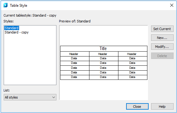
The command opens the Table style dialog box, in which you can create and change styles of .dwg tables.
Options:
|
Styles |
List of styles of .dwg tables in the document. It's content is regulated by the List drop-down list. |
|
List |
Determines what styles should be displayed in the Styles list: all styles or only styles in use. |
|
Preview of |
Preview window that displays an assumed view of the table created using style selected in the Styles list. |
|
Set current |
Makes current the style selected in the Styles field. |
|
New |
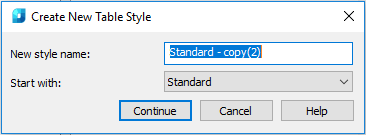
Opens the Create New Table Style dialog box to crate a new style based on that selected in the Styles field.
Clicking the Continue button opens the Modify Table Style dialog box as described below. |
|
Modify |
Opens the Modify Table Style dialog box to edit the style selected in the Styles field. |
|
Delete |
Deletes the style selected in the Styles field. |
To rename the style, double-click it in the Styles list.
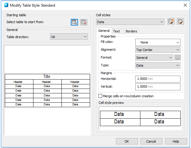
The Modify Table Style dialog box opens when editing the current or creating a new style.
Options:
|
Select table to start from |
Selects the table on the drawing to use as a sample when forming this table style. In the current software version the function is not realized. |
|
Table direction |
Sets the direction of placing data in the table. When selecting Down value, the table is created with data reading direction from top to bottom. When selecting Up value, the table is created with data reading direction from bottom to top. · Down. Title row and header row of columns are located in the top part of the table. If you select Insert rows and click Down, a new row is inserted below the current one. · Up. Title row and header row of columns are located in the bottom part of the table. If you select Insert rows and click Up, a new row is inserted above the current one. |
Cell styles
Is intended to determine a new cell style or change the current cell style. It is possible to create any number of cell styles.
|
Drop-down list of cell styles |
Selects and displays cell styles used in the table. |
|
|
Opens the Create New Table dialog box to create a new cell style based on that selected in the drop-down list. |
|
|
Opens the Manage Cell Styles dialog box. |


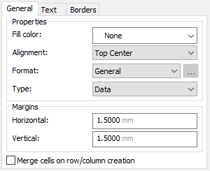
General tab
|
Fill color |
Specifies background color for cells. |
|
Alignment |
Specifies the text alignment in the table cells. Relative to upper and lower cells borders the text can be aligned center, top or bottom. The text can be aligned center, left or right relative to left and right cell borders. |
|
Format |
Determines the data type and formatting for table rows containing data column headers and table title. |
|
Type |
Determines the cell style: Label or Data. |
|
Horizontal |
Specifies the distance between text/block and left and right cell borders. |
|
Vertical |
Specifies the distance between text/block and upper and lower cell borders. |
|
Merge cells on row/column creation |
When creating a new row/column using the current cell style, the cells of this row/column are merged in one cell. Using this option you can create a title row in the top of the table. |
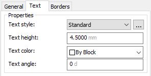
Text tab
|
Text style |
List of available text styles. Button |
|
Text height |
Specifies the text height. |
|
Text color |
Specifies the text color. |
|
Text angle |
Specifies the text rotation angle. It is possible to enter any angle from -359 to +359 degrees. |
 opens the
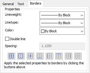
 Borders tab
|
Lineweight |
Assigns lineweight to borders, which are set using the Border button. When using wide lines, you may need to increase spaces from cell borders. |
|
Linetype |
Linetype to be applied to borders set by the user. Select Load to load the user linetype. |
|
Color |
Specifies color to be applied to borders specified by the borders selection button. |
|
Double line |
Displays table borders in form of double lines. |
|
Spacing |
Determines the spacing for borders displayed in form of double lines. |
|
Border buttons |
Applies weight and color of lines to all border or only to certain parts. |