

-
-
-
-
-
-
-
-
-
-
-
-
-
-
-
-
-
-
-
-
-
-
-
-
-
-
-
-
-
-
-
-
-
Separation by Type and Size
-
-
-
-
-
-
-
-
-
-
-
-
-
-
-
-
-
-
-
-
-
Separation by Type and Size
 Ribbon: Raster – Processing >
  Separation by size
Ribbon: Raster – Processing >  Separation Linear Objects
Ribbon: Raster – Processing >  Separate Text Areas
Menu: Raster – Processing the raster > Separation by size
Menu: Raster – Processing the raster > Separation Linear Objects
Menu: Raster – Processing the raster > Separate Text Areas
 Command line: SeparationBySize
Command line: SeparateLinearObjects
Command line: SeparateTextAreas
 This functionality is available only in the Raster module.
Selection operations allow you to transfer specific monochrome raster objects to new raster images placed on specified layers. From the original image, you can select hatches, text, linear objects and objects by size (isolated groups of adjacent points).
When performing an operation, the program finds objects of the specified type with the specified parameters in the image and transfers them to a new raster image. The new raster image created as a result of the operation has the same parameters (size, insertion point, resolution, scale) as the original one, but is placed on the specified layer. In this case, the loss of objects removed from the original image does not occur - they are simply moved to a separate raster layer.
The separation procedures can be used:
· instead of speckle remover, when it is necessary to save small-sized image objects, which the program can attribute to raster “garbage”;
· when it is necessary to use operations only to objects of a certain type, for example, editing texts or hatches.
After making selection, the displaced objects can be saved as a separate raster image, selected and returned to the original image, or the entire resulting raster layer can be deleted.
The order of performing object separation operations
· select the images to be processed. If no selection is made, the operation will be applied to all visible images located on unlocked layers;
· Run the appropriate command;
· In the dialog box that opens, configure the parameters by which the selection of objects will be carried out. The type and settings of the dialog box depend on the type of the selected object. The 

 buttons in the dialog boxes located next to the fields are designed to measure the set parameters in the image. To measure the object parameter in the image, click the button and indicate the required on the screen. The measured value appears in the corresponding field. The principle of filling in the Output layer field, in which it is necessary:
· enter the name of the layer on which the created image with the selected objects will be placed;
· set the color of the created layer by left-clicking on the color swatch located next to the field and choosing a color in the dialog box that appears.
· The settings results are controlled in the preview window of the dialog box. When satisfactory results are achieved, click Apply.
Setting parameters in the dialogs of object separation commands
Separation by size
· set the minimum and maximum size of objects in the corresponding fields;
· select linear objects;
· in the Max.width field, set the value of thickness of the raster line of objects to be selected;
· in the Max. break field, specify the ignored break size in lines.
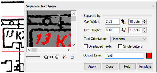
Separate text areas
· in the Max.width field, set the maximum line width of the raster text;
· in the Text Height field, specify the maximum size of an upper case letter in the text;
· in the Text Orientation field, select from the drop-down list the orientation of texts Horizontal, Horizontal and Vertical or Arbitrary Oriented;
· if necessary, check the boxes Overlapped texts and Single Letters.
Saving and deleting the created raster image
The created raster image with the selected objects automatically receives the status of embedded in the document and the name of the layer specified in the Output layer field.