

-
-
-
-
-
-
-
-
-
-
-
-
-
-
-
-
-
-
-
-
-
-
-
-
-
-
-
-
-
-
-
-
-
-
-
Separate Tab
-
-
-
-
-
-
-
-
-
-
-
-
-
-
-
-
-
-
-
-
-
-
-
Separate Tab
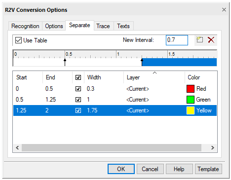
Using the Separation tab of the R2V Conversion Options dialog box, you can manipulate the properties of the vector objects being created: calibrate the thicknesses of the resulting vector objects, distribute vector objects corresponding to raster lines from the specified ranges of thicknesses to different layers and / or assign different colors to such objects.
Separate tab
Separation options
|
Option |
Description |
|
Use Table |
If this box is not checked, the program assigns the current property values (color and layer) to the objects; line weights of objects are set according to the thicknesses of the corresponding raster lines |
|
New Interval field and |
Allows you to create and delete thickness intervals in the table |
|
Table of thicknesses |
Allows you to edit intervals of objects thickness, assign color, layer and lineweight to the interval |
 buttons
Thicknesses Table
The criterion for dividing vector objects by layers and / or by colors is the thickness of the original raster lines.
The table specifies the intervals of widths of the image raster lines, which, during vectorization, will be converted into vector objects with a specified line width and a specific color, and then placed on the specified layers.
The thickness table can contain an arbitrary number of elements – thickness intervals. Each interval is determined by two values - the lower and upper boundaries of the thicknesses of vector objects that fall into this interval. Each interval is assigned properties (thickness, color and layer), which are assigned to objects with thicknesses that fall within the interval.
All intervals are created within the thickness range from zero to the Max. thickness specified in the Options tab of the same dialog box. The initial contents of the table are as follows:
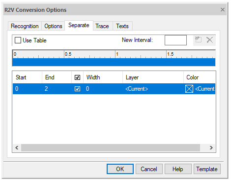
Original content of the thicknesses table
Creating a new interval in the thicknesses table
Enter the value of the upper limit of the thickness interval in the New Interval field, click  New Interval button.
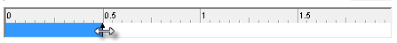
You can create an interval by left-clicking on the desired place in the thickness table ruler.
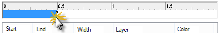
Creating a new interval in the thicknesses table
The existing interval, which contains the specified thickness value, will be split into two intervals. The properties of the new interval are inherited from the existing one. An arrow appears on the ruler to show the position of the upper boundary of the created interval.
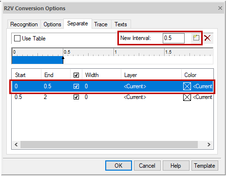
Specifying the upper limit of the specified interval
Changing the interval boundary
You can change the boundaries of all intervals, except for the upper boundary of the last and the lower first, which always have the Max. thickness and 0 respectively. Changing the upper (lower) boundary of the interval entails a change in the lower (upper) boundary of the adjacent interval. If you set the value of the upper (lower) boundary greater (less) than the value of the upper (lower) boundary of the adjacent interval, then this interval will be deleted.
Left-click on the row of the thickness table corresponding to the required interval, and then on the field in the Start or End columns in the selected row and change the value of the upper or lower boundary of the interval, or move the corresponding arrow on the ruler of the table of thicknesses.
Deleting interval in the table of thicknesses
In addition to the initial one, you can delete any interval.
Left-click on the row of the thickness table corresponding to the interval to be deleted, click  Delete Interval button or move one boundary arrow of the interval in the table ruler until it connects with another boundary arrow of the same interval. The interval will be deleted and one of the adjacent intervals will be given a new width value. If the movement occurs from left to right, then the width of the left adjacent interval increases; the width of the right adjacent interval increases as you move the cursor from right to left.
Changing interval properties
Each interval has the following properties: measured thickness (Start and End columns), specified Width, Color and Layer.
During the vectorization process, these properties will be assigned to objects that have a thickness within the given interval.
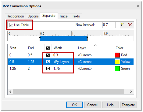
Interval properties
When the Use table box is checked, the value specified in the Width field is assigned to all vector objects whose width is within the specified interval.
If you do not need to round off the line thickness within the interval to the values preset in the Width field, clear the checkbox in the corresponding line of the interval properties.
Specify the interval width
Select with the mouse the row of the thickness table corresponding to the desired interval, and then click in the Width column.
Enter the required value.
Assign layer to interval
You can assign name of any layer to the interval or select Current. All vector objects with thicknesses within the specified range will be created on the specified layer. If there is no such layer yet, it will be created automatically during vectorization. When you select the Current layer, objects will be created on it.
Select with the mouse the row of the thickness table corresponding to the desired interval, and then click in the Layer column.
Select the existing layer in the list or enter the name of a new layer that will be created during vectorization.
Assign color to interval
You can assign any color to the interval, including Current, By Layer, and By Block. All vector objects that have thicknesses within the specified interval inherit the specified color. If Current is selected, objects of the specified interval will be created with the current color.
Select with the mouse the row of the thickness table corresponding to the desired interval, and then click in the Color column.
Select the color from the list or specify it in the dialog box that opens when you click the Other option.
Saving settings of the table of thicknesses
Settings of the table of thicknesses can be saved in the settings file.
Click the Template button, select Save.
In the Save Template File dialog box:
1. set the file name with .TPL extension;
2. click OK.
By default, the file will be saved in the Recognition options folder located in the root folder.
Loading setting of the table of thicknesses
Click the Template button, select Load.
In the Open template File dialog box:
1. specify the file name;
2. click Open.