

-
-
-
-
-
-
-
-
-
-
-
-
-
-
-
-
-
-
-
-
-
-
-
-
-
-
-
-
-
-
-
-
-
-
-
Recognition Tab
-
-
-
-
-
-
-
-
-
-
-
-
-
-
-
-
-
-
-
-
-
-
-
Recognition Tab
In this tab you can select a set of algorithms that will be used when vectorizing a raster image.
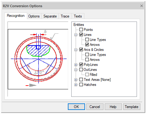
Recognition tab
Different types of raster images should be vectorized using different sets of entities. For example, to vectorize images of maps or sketches, you should use polylines that approximate raster curves of arbitrary shape, and when vectorizing engineering drawings - algorithms that create segments, circles, arcs, then the vector drawing will most accurately reproduce the original drawing.
To ensure the possibility of optimal recognition of images of different structure, the Graphics Editor uses several vectorization algorithms that recognize raster analogs of vector entities and generate approximating vector objects of the corresponding types. You can use one or more recognition algorithms in one vectorization operation.
The tree of algorithms is located in the right part of the Recognition tab. At the first level, there are recognition algorithms. To enable the desired algorithm, check the box next to its name. The second level of the tree contains additional functions and parameters of the corresponding algorithms.
The vectorization process is also directly influenced by the geometric recognition parameters located in the Options tab of this dialog box.
Points
This algorithm is used to recognize geodetic marks and similar labels on specific images, for example, on geographic maps.
The graphics editor recognizes as a point an object with dimensions of at least 2x2 pixels (smaller objects are considered “speckle” and are deleted) and no more than the Max. thickness vertically and horizontally.
The Point type object can be recognized only in an automatic mode.
It is not recommended to use this algorithm when recognizing images of low quality or containing many small spots and “speckle”.
Lines
Includes line segment recognition algorithm. As a result of the algorithm wor, straight lines are created.
The figure illustrates the results of vectorization using a single enabled Lines algorithm. The original raster fragment is shown on the left; the right drawing shows the result of vectorization with disabled display of object thicknesses.


Lines vectorization
It has the following additional options:
· Arrows – when the option is enabled, it recognizes dash and dash-dot straight lines, creating vector lines with the corresponding line type;
· Line Types - when the option is enabled, it recognizes raster analogs of dimension lines (lines with one or two arrows at the end points) and, if the arrows are found, saves them as end markers of the line.
This algorithm is influenced by the following parameters of the Options tab.
The algorithm recognizes raster objects, the length of which is greater than the value of the Min. length option, and thickness is less than the value of the Max. thickness option.
The Max. break option sets the maximum length of an ignored raster line break.
The Approximation Accuracy option sets the accuracy of approximation of raster lines by vector objects. If the raster quality is poor, the option value should be decreased so that the algorithm recognizes raster objects with significant shape distortions.
When the Orthogonalization parameter is activated, the recognized line segments are aligned parallel and perpendicular to the direction specified in the Base angle field. Sections with small angles of deviation from the corresponding directions are aligned. The acceptable deviation for orthogonalization is determined by the Accuracy parameter. The closer this parameter is to the Low value, the greater the deviation can be.
Arcs and circles
Enables the algorithm for recognizing raster circles and arcs.
The figure illustrates the results of vectorization using the Lines and Arcs and Circles algorithms. The original raster fragment is shown on the left; the right drawing shows the result of vectorization with disabled display of object thicknesses.


Circle vectorization
It has the following additional options:
· Arrows – when the option is enabled, the program searches for raster analogs of dimensional arcs (arcs with one or two arrows at the end points) and, if arrows are found, creates the corresponding dimensional objects;
· Line Types - when the option is enabled, the program recognizes dash and dash-dot arcs and circles, creating vector objects with the appropriate line type.
This algorithm is influenced by the following parameters of the Options tab.
The algorithm recognizes raster circles and arcs that are larger than the Min. length, and thickness is less than the value of Max. thickness.
The Max. break option sets the maximum length of an ignored raster arc and circle break.
The Approximation Accuracy option sets the accuracy of approximation of raster arcs and circles by vector objects. If the raster quality is poor, the option value should be decreased so that the algorithm recognizes raster objects with significant shape distortions.
Polylines
This algorithm approximates the center lines of raster objects by polylines. The algorithm creates polylines consisting of straight segments only. You can use this algorithm alone or in conjunction with the Outlines algorithm when vectorizing maps and other images consisting of arbitrary lines (i.e., hand-drawn lines).
It has the following additional options:
· Line Types - when this option is enabled, the program recognizes dash and dash-dot arcs and circles, creating vector objects with the appropriate line type;
· Create Vertex on Intersection - when this option is enabled, the algorithm creates vertices at the intersections of polylines.
This algorithm is influenced by the following parameters of the Options tab.
Max. length determines the maximum length of the recognizable segment added to the polyline. Longer segments are not added to the polyline. This allows, for example, to trace curved contours on maps that intersect with coordinate lines; the algorithm automatically stops at the intersection of the traced contour with a long straight coordinate grid line.
Approximates raster lines that are thinner than the Max. thickness.
The Max. break option sets the maximum length of an ignored raster line break.
The Approximation Accuracy option sets the accuracy of the raster curve approximation by the vector polyline.
Outlines
This algorithm is designed to approximate the outlines of filled areas by polylines by creating closed polylines that approximate the boundaries of raster objects. Contour polylines consist of straight segments only.
The figure shows the results of vectorization using the only enabled Outlines algorithm. The original raster fragment is shown on the left; on the right there is the result of vectorization.

Outlines vectorization
This algorithm is influenced by the following parameters of the Options tab.
The algorithm approximates raster lines that are thicker than the Max. thickness. To get the outlines of all raster objects, enable only this algorithm and set the Max. thickness equal to zero.
The Max. Break option sets the maximum length of an ignored raster line break.
The Approximation Accuracy option sets the accuracy of approximating the raster object boundaries by vector polylines.
Text areas
Enables the text recognition algorithm. The program finds image fragments containing raster texts and applies an operation specified as an additional parameter of the algorithm to the found texts.
The settings of search for raster texts and the OCR module are configured in the Texts tab of the same dialog box. The setting is described below in this chapter.
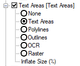
Options of text areas vectorization
· None – does not vectorize raster texts. Areas containing found raster texts are not vectorized.
· Text Areas – creates vector rectangles that limit raster texts. Areas containing found raster texts are not vectorized. Vector texts can be entered manually using the procedure for viewing and correcting recognized texts described later in this chapter.
· Polylines – approximates the center lines of raster texts with polylines.
· Outlines – approximates the boundaries of raster texts with outline polylines.
· OCR – recognizes raster texts and creates text objects.
· Raster – recognizes raster texts without creating vector text objects.
The algorithm uses the values in the Text Height list of the Options tab as the maximum height of upper case raster text characters.