-
-
-
-
-
-
-
-
-
-
-
-
-
-
-
-
-
-
-
-
-
-
-
-
-
-
-
-
-
-
-
-
-
-
-
-
-
Plot Preview
-
-
-
-
-
-
-
-
-
-
Plot Preview
The right part of Page Setup and Plot dialogs is the window for preview of the specified plot setups.
Change of plot setups is dynamically displaed in the preview window.
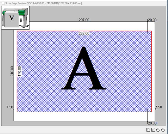
The preview window provides two options for displaying the specified plot area: schematic (simplified) and normal, in which the plot setting is displayed in the view it will be output to the plot device.
Conventions in schematic (simplified) preview:
Dashed line – the plot area boundaries for the selected plot device and specified paper format.
Numbers – size of the specified paper format and indentations to the plot boundary. Indentations from the paper edge to the plot boundaries depend on the selected plot device.
Blue hatch and letter A – location and orientation of the specified plot area on the page.
Red line – warning that the specified plot area is outside the plot margins.
|
|
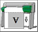
The icon with printer image (in schematic symbol in preview window) that displays the positioning of the specified plot area on a paper page. The arrow shows the direction of paper exit at plotting. |
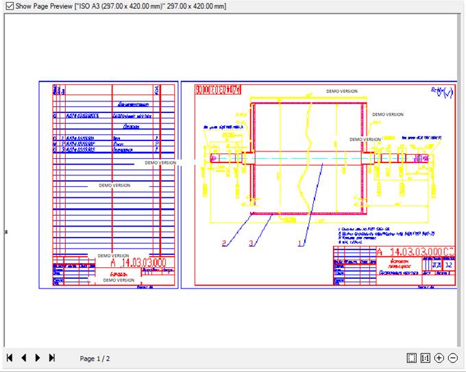
Switching of schematic symbol in the preview window to a normal one and vice versa is carried out by selecting/removing Preview checkbox, located above the preview window; the information about the specified paper format is also displayed here:

attention! For a layout that does not have an assigned plotter, preview is not available.
Options of the preview dialog box (for normal view):
|
|
Zoom all |
Button to display the whole specified plot area in the preview window. |
|
|
Zoom 1:1 |
Button to display the specified plot area at a scale of 1:1. |
|
|
Zoom in |
Button to zoom in the image in the preview window. |
|
|
Zoom out |
Button to zoom out the image in the preview window. |
|
|
|
|


Additional options displayed for a multipage plot:
|
|
First page |
Button to display the first page of a plot set in the preview window. |
|
|
Previous page |
Button to display the previous page of a plot set in the preview window. |
|
|
Next page |
Button to display the next page of a plot set in the preview window. |
|
|
Last page |
Button to display the last page of a plot set in the preview window. |


|
|
Displays the number of the page viewed in the preview window, and the total number of pages of the plot set. |

It is possible to zoom and pan an image in the preview window by a mouse after clicking inside the window:
· to zoom an image – rotate the mouse wheel.
· to pan an image – move the mouse with the left or right button pressed and held, as well as with a mouse wheel.
A separate Plot Preview dialog box with normal view of the plot set can be opened from:
 Ribbon: Output – Plot >
  Preview
Menu: File –  Preview…
Toolbar: Main –
 Hot keys: CTRL+F2
Command line: PREVIEW
In the Batch plot dialog box, the Plot preview is opened by Preview button.
The possibility of quick plot of the content using the Plot button is added to the parameters of the preview window in the Plot Preview dialog box:
|
|
Setting the number of copies to print. |
|
||
|
|
Plot |
The button to plot. |
||

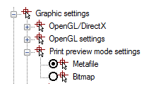
When plotting individual files (with rich graphics, a large number of viewports, etc.) the message “Not enough memory to create preview” can appear in the preview window. In this case it is necessary to change the setting in the Print preview mode settings section (Graphic settings item of the Options dialog box).
By default, the Metafile (WMF) parameter is set: