

-
-
-
-
-
-
-
-
-
-
-
-
-
-
-
-
-
-
-
-
-
-
-
-
-
-
-
-
-
-
-
-
-
-
-
-
-
Page Setup Manager
-
-
-
-
-
-
-
-
-
-
Page Setup Manager
 Ribbon: Output – Plot >
  Page Setup Manager
Menu: File –  Page Setup Manager …
 Toolbar: Main –
 Command line: PAGESETUP
When preparing a document for printing, it is necessary to set a sufficiently large number of parameters for each layout: select the printer, specify the paper size and orientation, set the plotting scale, etc. The Page Setup Manager allows you to save plot setup parameters in the named page setups. The use of named page setups makes it possible to significantly reduce the time for preparing documents to plot due to applying previously made plot settings to new document layouts.
With help of Page Setup Manager, it is possible to create new setups, edit those previously created in the current document or imported from other documents. The page setups are assigned to each document page and are stored in a document file.
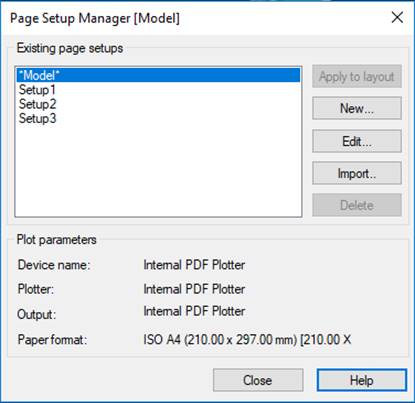
Upon starting the command, the Page Setup Manager dialog box opens. The name of the current layout is displayed in the dialog box title in square brackets:
Options:
|
Existing page setups |
In the top left part of the section the list of page setups applicable to the current layout is displayed. In the absence of created page setups in the document, the list displays only the current layout name, marked with asterisks (for example, *Model*, *Layout1* etc.), to which created or imported page setups may be applied. |
|
|
Button to assign the page setup selected in the list to the current layout. The layout name is added with the name of assigned page setup in parentheses, for example, *Model(Setup1)*, *Layout1(Setup2)* etc. note: When selecting the current layout in the list, the Apply to layout button is not available. |
|
|
Button for opening New Plot Set button, where it is possible to select an earlier created setup as a template and enter a name for the new setup. |
|
|
Button for opening Page Setup dialog box for editing settings for the selected setup. |
|
|
Button for opening a standard dialog box for selecting files, where it is possible to select a file to import one or more page setups from it. |
|
|
Button to delete the selected page setup. |
|
Plot parameters |
Displays information about the selected page setup. |
|
Device name: |
Name of the plot device assigned to the setup. |
|
Plotter: |
Type of the plot device assigned to the setup. |
|
Output: |
Physical location of the plot device assigned to the setup. |
|
Format: |
The name of paper format parameters assigned to the setup. The paper size and orientation are displayed in square brackets [ ]. note: The name of the paper format can include the paper size, which is displayed in round brackets ( ). |


note: The page setups created for the layout space are not applied to the model space. Conversely, the page setups for the model space cannot be applied to the layout space.
To create the page setup:
1. Click the New button.
2. In the opened New Plot Set dialog box
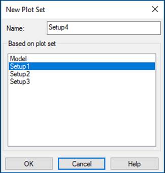
in the Based on plot set section, select a previously created setup as a template.
3. In the Name field, enter the name of a new setup.
note: By default, for a newly created page setup the following name is proposed SetupN, where N is the number of the setup being created. For convenience it is recommended to assign a user name to the new setup, which displays the format name and orientation, assigned plotter name, etc., for example, A4 (portrait) PDFCreator or A1 (landscape) CanonLargeFormat W7250.
4. Click OK button.
5. Specify the necessary parameters in the Page setup dialog box and click OK button.
The newly created setup is displayed in the Existing page setup list of the Page Setup Manager.
To edit the page setup:
1. Select the setup for editing in the Existing page setup list.
2. Click the Edit button.
3. Make the required changes of parameters in the opened Page Setup dialog box.
4. Click OK button.
To import the page setup:
1. Click the Import button.
2. In the opened standard file selection dialog box, select the type of file, folder in which it is located, and the file itself.
note: It is possible to import page setups from the drawing format (*.dwg), drawing template (*.dwt) and drawing interchange format (*.dxf).
3. Select one or more page setups in the Import page setup dialog box (using the SHIFT and CTRL keys).
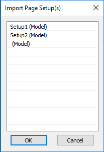
4. Click OK button.
To delete the page setup assigned to the current layout:
1. Select the page with an assigned setup in the Existing page setup list, for example, *Model(Setup1)*.
2. Click the Edit button.
3. In the Page Setup dialog box choose the None option in the available plot devices list.
4. Click OK button to close the dialog.
5. In the Page Setup Manager dialog box, the name of the assigned setup will be deleted from the page name, i.e. the page name for the above example will be: *Model*.
6. Click to select the page setup (Setup1 in this case). The disabled Delete button becomes available (enabled).
7. Click the Delete button.
8. To close the dialog, click the Close button.
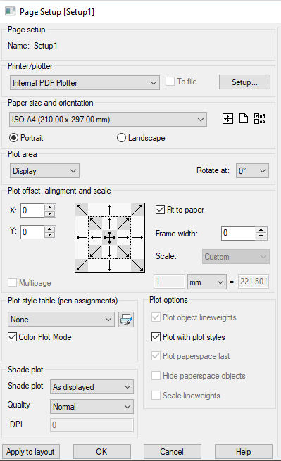
The Page Setup dialog is opened from the Page Setup Manager at creating or editing a page setup (the New and Edit buttons):
Options:
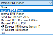
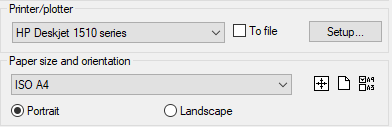
Printer/Plotter
|
|
Drop-down list that displays the available plot devices. |
|
|
|
|
To file |
Turns on/off the print mode into the plt-file. When To file option is turned (checkbox is selected), clicking the Plot button (in the Plot dialog box) opens the Plot to file dialog box (standard dialog box to store files) to select the folder for storing plt-file. |
|
|
Button to open the dialog box to modify the current settings of the selected plot device. The view of the opened dialog box and configuration settings are determined by the driver of the current plot device. |

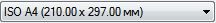
Paper size and orientation
|
Portrait Landscape |
Drop-down list to select paper formats for the current plot device. Setting the paper orientation |
|
|
Button for automatic search of the optimal paper format for the specified plot area and the selected plot device from the plotting fields. The selected optimal paper format allows you to print the defined plot area without cutting in boards. Attention: The size of the optimal paper format selected in this way should be checked against the size of paper actually used in the plot device. |
|
|
Button to set parameters of a new paper format. Opens the Modify paper format dialog box. |
|
|
Button to create a set of paper formats to be included in the Paper size and orientation drop-down list. Opens the Edit paper list dialog box. |


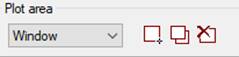
Plot area
|
Model Layout
|
Drop-down list to select the drawing area to be plotted. The list view depends on the current Model or Layout space.
|
|
Options for setting the plot area: |
|
|
Display |
Plots the view in the current viewport in the model space and in the current view in the layout space. |
|
Extents |
Plots the drawing’s portion that currently contains objects. All objects of the current space are plotted. |
|
Limits |
Plots the document objects within the set grid limits (Grid > Drawing limits). The option is available in the Model space. |
|
Layout |
Plots all objects located in the layout. The option is not available in the model space. |
|
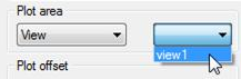
View
|
Plots the named view. The named view is selected from the drop-down list:
note: If the document does not contain named views, the option is not displayed in the drop-down list. |
|
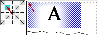
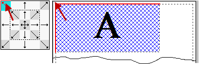
Window |
Specifies the plot area by a rectangular selection window. When selecting this option, the dialog box is temporary closed and in response to the command line prompt: Specify First Corner or [Select]: it is possible to specify the plot area on the display by indicating two opposite corners of the rectangle. The Select option allows you to specify the plot area by selecting one side of the frame that limits the paper format. In this case the size and orientation of the plot area is determined by the parameters specified in the Paper size and orientation section. After specifying the first plot area by the window, additional buttons are displayed in the dialog box:
|
|
Turn |
Drop-down list to select a turn angle of the specified plot area. Angles of 0, 90, 180 and 270 degrees are available for selection. |


Plot offset, alignment and scale
|
|
Field to specify the offset value of the plot area relative to the lower left corner of plotted page in the X direction. |
|
|
|
Field to specify the offset value of the plot area relative to the lower left corner of the plotted page in the Y direction. |
|
|
attention! Offset is specified when the alignment mode is disabled. To disable the alignment mode, it is necessary to click repeatedly the highlighted arrow button on the alignment icon. |
||
|
|
The icon with buttons of alignment of the plot area on the sides of the paper format. The buttons bounded by a dashed line produce a shift of the plot area to indentations determined by the plotter’s print margin.
Buttons of the outer frame shift the plot area to the edges of the selected paper, margins of indentation to the plotter’s print margins are ignored.
The central button |
|
|
Multipage |
Turns on/off the multipage plot mode. The mode is used to print large formats on printers that do not support such formats. For example, for plotting A1 format on A4 printer. The option is available, when Fit to paper option is off. |
|


 controls the automatic determination of offsets in X and Y direction so that the drawing is located in the page center (automatic drawing centering).
Plot scale
|
Fit to paper |
Turns on/off the mode of adjusting the plot area scale so that it perfectly fits the page of current format. |
|
Frame width: |
Option to set the parameter of considering weight of the frame line defining the drawing boundaries and coinciding with the plot area boundaries. When setting a parameter value equal to the frame line weight, the frame is printed without reducing its thickness. For example, if the parameter value is equal to zero, the frame created by lines of 1 mm weight will be printed at 0,5 mm thickness. When setting the parameter to 1 mm value, the frames will be printed at 1 mm thickness. note: The Frame width option works only when the Fit to paper mode is on. |
|
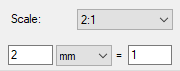
Scale:
|
Drop-down list to select the standard scale values. Selecting measurement units (inches or mm) and setting the plot scale. |
Plot style table
|
|
Drop-down list to select the plot style table. |
|
Color Plot Mode: |
Manages the display of plot style tables in the drop-down list for selecting the plot style table. When the checkbox is switched on, the list displays the color plot styles (*.ctb), when the checkbox is off – the named ones (*.stb). |
|
|
Button to open the Plot Style Table Editor dialog box to edit the specified plot style table or create a new one. |

Shaded viewport
|
Shade plot: |
Drop-down list to select the plotting option for shaded and rendered 3D models. Available options are: · As displayed – Objects are plotted as they are displayed on the screen. · Wireframe – Only objects in wireframe are plotted, regardless of the way they are displayed on the screen. · Hidden – Hidden lines of objects are not plotted, even if they are displayed on the screen. · Rendered – Plots the objects as rendered, regardless of the way they are displayed on the screen. |
|
Quality: |
Drop-down list to select quality options for plotting shaded and rendered viewports of 3D models. Available options are: · Draft – Plots objects in a wireframe mode. · Preview – Plots objects at the ¼ of the current plot device resolution (maximum – 150 dpi). · Normal – Plots objects at the ½ of the current plot device resolution (maximum – 300 dpi). · Presentation – Plots objects at the current resolution of the plot device (maximum – 600 dpi). · Maximum – Plots objects at the current plot device resolution with setting no maximum limit. · Custom – Plots objects at the resolution, which is specified in the DPI box. The resolution specified by the user cannot exceed the current resolution of the plot device. |
|
DPI: |
Field to specify the plot resolution. The option is available, when selecting the Custom option in the Quality list. |
Plot options
The section to specify options that allow switching between ready-configured plot-style (*.ctb or *.stb files) and customized settings for the display properties of objects in the current document.
|
Plot object lineweights |
Turns on/off the plot mode considering the lineweights assigned to objects and layers. |
|
Plot with plot styles |
Turns on/off the plot mode considering the plot styles assigned to objects and layers. When selecting this option, the Plot Object Lineweights option is also enabled automatically. |
|
Plot paper space last |
Turns on/off the mode to plot model space objects first. |
|
Hide paper space objects |
Turns on/off the mode that applies Hide command to objects in the paper space viewport. The option is available only for a layout space. The option is active only when plotting and in the preview of plot results. |
|
Scale lineweights |
Turns on/off the mode of scaling lineweights to plot from the Layout space. Lineweight changes in accordance with the scale specified in the Scale section. |
Buttons to manage the specified plot setups
|
|
Button to apply the named page setup to the current layout. The name of the page setup applied to the layout is displayed when plotting this page in the title of the Plot dialog box. |
|
|
Button to save settings and move to the Page Setup Manager dialog box. |
|
|
Button to close the dialog without saving the plot setups. |


Saving Plotter Settings to PC3 File
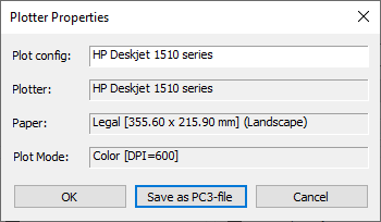
The drop-down list in the Plotter section contains a list of all plotters registered in the system. Their parameters are edited by clicking Setup button to the right of the list.
The settings dialog that opens is individual for each printing device. When you finish changing the settings, when you close the dialog, you will be prompted to save the settings as a separate file with the PC3 extension so that you can reuse it.
After that, the saved configuration can be selected in the list of printers.
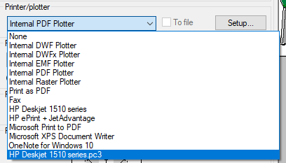
A file of the same name with the PC3 extension will appear in the plot configuration files directory.
Such plotter configurations can be transferred to different computers and shared among team members, provided that they use the same driver version and plotter model. If you update the plotter driver version, the old PC3 file may not work. Plot configurations for system plotters can also be shared, but should be in the same version of the operating system.
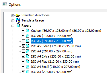
Modifying and Adding the Paper Formats
The composition of paper formats list of the Paper size and orientation section in Plot and Page Setup dialog boxes depends on formats specified in the Papers section of Options dialog (the Tools menu– Options). In the same section it is possible to change the existing paper format or create a new one.
To edit the list of paper formats:
1. Enter the Papers section of the Options dialog box.
2. Set the label of formats that should be displayed in the list:
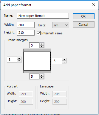
To add a new paper format:
1. Select the Papers section name of the Options dialog box. To create a new paper format based on the existing one, select the required format in the section list.
2. Click the Add button.
3. In the opened Add paper format dialog box:
· specify the new format name;
· select the measurement units;
· enter the values of format width and height;
· if necessary, set size of the internal frame: set the Internal frame mark and specify the values of margins from the format edge in the Frame margins section:
note: The plot area sizes are set depending on the specific plot device used, as they are determined by the plot device manufacturer.
note: When setting the paper size, it is necessary to consider the minimum and maximum acceptable sizes for the specific plot device used, which are also determined by the plot device manufacturer.
4. Click OK to close the dialog box.
5. Click OK to close the Options dialog box.
To modify a paper format:
1. Enter the Papers section of the Options dialog box.
2. Select the format to be modified.
3. Click the Modify button.
4. In the opened Modify paper format dialog box, repeat actions of 3-5 items from the previous section. You should not change the format name.
The newly created paper formats are displayed in the Paper size and orientation drop-down list in the Plot and Page Setup dialog boxes after selecting a specific plot device.
attention! The paper formats for which the specified sizes are more or less than those acceptable for a specific plot device are not displayed in the Paper size and orientation list for this device.
Editing the List of Paper Formats
The content of the drop-down list for selecting paper formats of the Paper size and orientation section in the Plot and Page Setup dialog boxes can be edited.
The  Filter paper button of the Paper size and orientation section opens the Edit paper list dialog box, in which it is possible to disable the unused formats, enable additional ones or delete paper formats that belong to the custom formats list.
The dialog box contains the list of all available paper formats that can be included in the list.
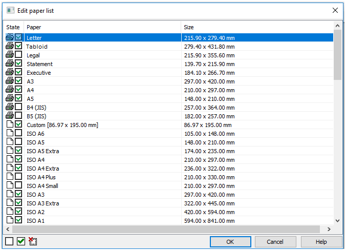
Options:
|
State |
|
Paper format belongs to the list of formats of the selected plot device. |
|
|
|
Paper format belongs to the list of custom formats nanoCAD. |
|
|
|
Format is included in the list. |
|
|
|
Format is deleted from the list. |
|
Paper |
Names of standard and custom paper formats. |
|
|
Size |
Sizes of standard and custom paper formats. |
|


To edit the list of paper formats:
1. Select the format in the dialog box.
2. Select/clear the checkbox  in the State column or use the dialog buttons:
 Turn off paper
 Turn on paper
 Delete custom paper
note: Paper formats that belong to the current plot device and are marked with  cannot be deleted.
To edit the status or delete several formats at once use the multiple selection:
· While holding down SHIFT key, select all formats located between the first and the last left click.
· While holding down CTRL key, it is possible to add any format from the list by left click.
attention! Editing in the Paper formats list editor dialog box is synchronized with the Papers list of the Options dialog box (the Tools menu – Options). The custom formats are deleted simultaneously from all format lists.