

 De
De  Es
Es  Fr
Fr  Pt
Pt 

-
-
-
-
-
-
-
-
-
-
-
-
-
-
-
-
-
-
-
-
-
-
-
-
-
-
-
-
-
-
-
-
-
Node Note
-
-
-
-
-
-
-
-
-
-
-
-
-
-
-
-
-
-
-
-
-
-
Node Note
 Ribbon: Home, Annotate – Leaders >
  Node note
Menu: Draw – Notes >  Node notes…
Toolbar: Utilities, Notes –
 Command line: NLD, NLEADER, NOTEK
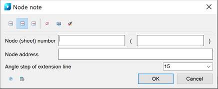
This command opens the Node note dialog box to set the note options:
Options:
Use the icons to select the text alignment method:
|
|
|
By left edge. |
|
|
|
By center. |
|
|
|
By right edge. |


Other icons and options:
|
|
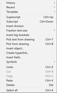
The Insert special symbol icon opens the panel with the table of special symbols, to select and insert them at the current cursor position in the text input field. |
|
|
The Notepad icon opens the Notepad dialog box. |
|
|
The Match properties icon temporarily closes the dialog box to specify the inserted leader whose properties should be copied and applied to the newly-created leader. |
|
Node (sheet) number |
An input line consisting of two fields to indicate the Node and Sheet number. |
|
Node address |
Input line to specify the Node Address. |
|
Inclination step of extension lines: |
Drop-down list to select the inclination. In the list the following inclinations are available: · Custom - the extension line is placed arbitrarily (by default); · 15 - the extension line is placed in step multiples of 15°; · 30 - the extension line is placed in step multiples of 30°; · 45 - the extension line is placed in step multiples of 45°; · 90 - the extension line is placed in step multiples of 90°. |
|
|
The Options button opens the nanoCAD Design Settings dialog box – Symbols tab |


The node note contains two input lines by default. The first input line consists of two fields for specifying the Node (sheet) number. The second input line is for specifying the Node Address.
Right-click in the text field and choose the required menu item:
When you open the context menu on a leader arrow (without selecting the leader), a dialog box for selecting the arrow type will appear:
To create a node note:
The Show dialog before inserting the object option is enabled
1. Run the command.
2. In the Node note dialog box, select the required note options.
3. Enter the required text into the text fields.
4. Click OK.
5. Specify the oval/circle center.
6. Specify the oval/circle size.
7. Place the landing in the drawing.
The Show dialog before inserting the object option is disabled
1. Run the command.
2. Specify the center of the leader oval/circle.
3. Set the size of the leader oval/circle.
4. Place the leader landing on the drawing.
5. In the Node note dialog box, select the required note options.
6. Enter the required text into the text fields.
7. Click OK.