

 De
De  Es
Es  Fr
Fr  Pt
Pt 

-
-
-
-
-
-
-
-
-
-
-
-
-
-
-
-
-
-
-
-
-
-
-
-
-
-
Insert Underlay
-
-
-
-
-
-
-
-
-
-
-
-
-
-
-
-
-
-
-
-
-
-
-
-
-
Insert Underlay
 Ribbon: Insert – Reference >
  Underlay…
Menu: Insert >  Underlay…
 Command line: UATTACH
Insert DWF, DWFX or PDF underlays to the drawing. In case if 3D Module is available, the following 3D formats can be inserted:
|
Format |
Version |
|
Parasolid (*.x_t; *.x_b) |
25.0 |
|
IGES (*.igs; *.iges) |
5.3 |
|
STEP (*.step; *.stp) |
203, 214 |
|
ACIS (*.sat) |
22.0 |
|
VRML (*.wrl) |
2.0 |
|
STL (*.stl) |
- |
|
|
Note |
|
Date from inserted PDF underlays can be further converted into a document by the Convert PDF command. |

|
|
Note |
|
"Marks" (text comments, annotations, highlights, vector graphics that are added to a PDF file on top of the main content in a third-party editor) are visible in the Insert Underlay dialogs, on-screen, and in print, but are not imported or used as anchor objects. |

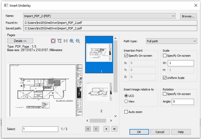
Options:
|
Name: |
List of inserted underlays’ names. |
|
|
Opens Select Underlay file dialog to select and insert new underlay. |
|
Found in |
Displays information about the path by which the underlay file was found. |
|
Saved path: |
Displays information about the saved path to the underlay file. |
|
Path type: |
Information about path of underlay file. The following options are available in the drop-down list: · Full path · Relative path · No path For methods of specifying the path to the folders where files are stored, see Inserting External References section. |

Insertion point
|
Specify on-screen |
Selects the insertion point after the dialog box is closed. |
|
X: Y: Z: |
Specifies the point coordinates for the underlay insertion. |
Scale
|
Specify on-screen |
Specifies the scale of underlay after the dialog box is closed. |
|
W: |
Width scale factor. |
|
H: |
Height scale factor. |
|
Uniform scale |
Specifies the scale factor for the Width or Height values. A value specified for Width is also reflected in the Height value. |
Rotation
|
Specify on-screen |
Specifies the rotation angle for the inserted underlay, using the pointing device. |
|
Angle: |
Sets the rotation angle for the inserted underlay. |
Insert image relative to
|
UCS |
Sets the insert underlay mode relative to the User Coordinate System (UCS). |
|
View |
Sets the insert underlay mode relative to the World Coordinate System (WCS). |
|
Auto zoom |
Switches on/off the full screen mode of the inserted underlay. |
Pages
|
|
Shows/hides underlay page information (type, size, layer). |
|
|
Zoom and pan buttons in preview dialog. |
|
Selected |
Numbers of selected pages to insert. |
|
|
Buttons for transition between pages in underlay. |


You can also insert an underlay by dragging the file with the mouse (drag&drop) from the explorer into the graphic area of the drawing.