
 De
De  Es
Es  Fr
Fr  Pt
Pt 

-
-
-
-
-
-
-
-
-
-
-
-
-
-
-
-
-
-
-
-
-
-
-
-
-
-
-
Edit References
-
-
-
-
-
-
-
-
-
-
-
-
-
-
-
-
-
-
-
-
-
-
-
-
-
-
Edit References
 Ribbon: Insert – Reference >
  Edit reference
Menu: Tools – External reference or context edit block >  Edit reference
 Command line: REFEDIT
Double-clicking on an external reference insertion
The use of external references significantly eases the work and allows you to quickly combine multiple drawings in a single document. To make work with external references more convenient, you can edit the references directly in the current drawing to which they are added.
To edit a referenced drawing from within the current drawing, you should use the working set to identify objects that belong to the external reference or block insertion rather than the current drawing. The working set includes only the objects belonging to the reference selected for editing.
You can add or remove objects from the working set. If you create a new object while editing a reference, it is almost always added to the working set automatically. Editing changes in the working set can be stored in the source file of the external reference or block insertion.
Start the Edit reference command. In the command line you can see:
Select reference or block insertion or [All insertions]:
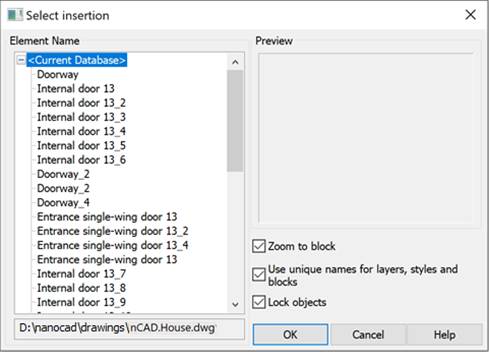
Select the external reference on the drawing and in the Select insertion dialog box that opens, choose the objects to edit:
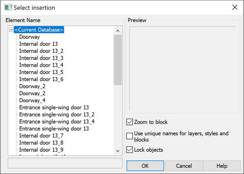
If you select the All insertions option in the command line, the Select insertion dialog box opens immediately and in the Element Name section all references and blocks inserted into the drawing will be displayed:
|
Parameter |
Description |
|
Zoom to block |
Switches on/off the mode to display the selected reference on the screen. |
|
Use uncial names for layers, styles and block |
Controls whether layers and other named objects extracted from the reference are uniquely altered. If selected, named objects in external references are altered (names are prefixed with $#$), similar to the way they are altered when you bind external references. If cleared, the names of layers and other named objects remain the same as in the reference drawing. Named objects that are not altered to make them unique assume the properties of those in the current host drawing that share the same name.
|
|
Lock objects |
Locking objects that are not in the working set. Locked objects are not editable, which prevents objects in the source drawing from being accidentally changed in reference edit mode. |
You can open the Select insertion dialog to edit a specific reference by double-clicking the left mouse button on the link in the program’s workspace
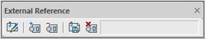
After selecting objects for editing and clicking OK, the External Reference toolbar will appear automatically.
Drawing objects not in the working set are shaded (displayed in a fainter color) when editing references (blocks or external references). Reference objects and objects added to the working set appear visually normal on the screen.
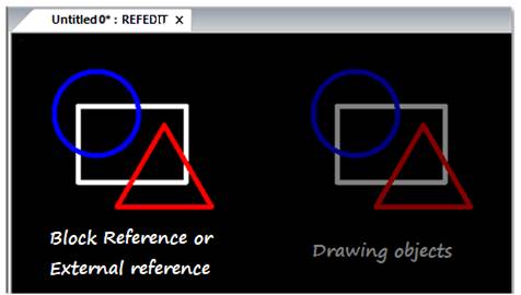
To indicate the mode of reference edit, a Reference Editor labelis added to the document name in the tab, separated by a colon.
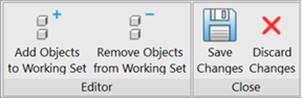
An additional Reference Editor tab appears on the ribbon:
In the classic interface, the External Reference toolbar appears:
A toolbar (widget) also appears in the drawing’s graphic area:

Using the tab/toolbar/widget buttons, you can add or remove objects from the working set, as well as save or discard changes made to the reference.
|
|
Attention |
|
In edit references mode you MUST NOT (!) close neither a document with edited reference nor nanoCAD till all changes are saved or discarded (Save and Close or Discard and Close buttons on the Refedit toolbar). |

After saving or discarding all changes the External Reference toolbar closes and a document tab returns to its original view.
Add Objects to the Working Set
Menu: Tools – External reference >  Add objects to working set
Toolbar: External Reference –
Command line: REFSETA
Use this command to transfer the objects from the current drawing to the working set.
Remove Objects from the Working Set
Menu: Tools – External reference >  Remove objects from working set
Toolbar: External Reference –
Command line: REFSETR
Use this command to remove selected objects from the working set.
IDH_RefCloses
Save External Reference Changes
Menu: Tools – External reference >  Save and close
Toolbar: External Reference –
Command line: REFCLOSES
The command saves the changes made to the insertion, closes the Edit Reference tab (the External Reference toolbar), and exits the insertion editing mode (as evidenced by the disappearance of the REFEDIT label (*) in the document tab).
IDH_RefClosed
Discard External Reference Changes
Menu: Tools – External reference or context edit block >  Discard changes
Toolbar: External Reference –
Command line: REFCLOSED
The command undoes the changes made to the insertion, closes the Edit Reference tab (the External Reference toolbar), and exits the insertion editing mode (as evidenced by the disappearance of the REFEDIT Editor label (*) in the document tab).