

-
-
-
-
-
-
-
-
-
-
-
-
-
-
-
-
-
-
-
-
-
-
-
-
-
-
-
-
-
-
-
Multileader Style Manager
-
-
-
-
-
-
-
-
-
-
-
-
-
-
-
-
-
-
-
-
-
-
-
-
Multileader Style Manager
 Ribbon: Home, Annotate – Leaders –
Toolbar: Mleaders – 
 Command line: MLEADERSTYLE
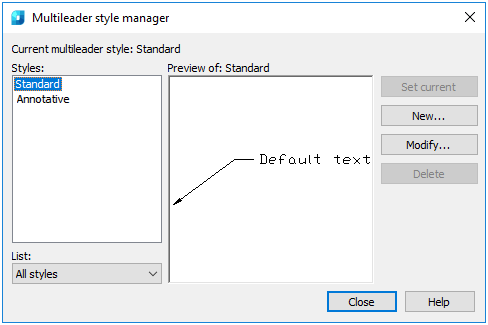
The command opens the Multileader Style Manager dialog box, where it is possible to create and modify the multileader styles.
Multileaders are created with the style displayed in the drop-down list on the Mleaders panel or on the ribbon in the Draw tab in the Leaders group.
Options:
|
Styles |
List of multileader styles in the document. Its content is regulated by the List drop-down list. |
|
List |
Specifies what styles should be displayed in the Styles list: all document styles or only current ones. |
|
Preview of |
A preview window that displays the assumable image of the multileader created with use of style selected in the Styles list. |
|
Set current |
Makes current the style selected in the Styles field. |
|
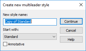
New |
Opens the Create New Multileader Style dialog box to create a new style based on that selected in the Styles field.
Clicking of the Continue button opens the Modify Multileader Style dialog box described below. |
|
Modify |
Opens the Modify Multileader Style dialog box to edit the style selected in the Styles field. |
|
Delete |
Deletes the style selected in the Styles field. |
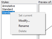
A context menu is also available in the Styles field. In addition to the listed actions, there it is possible to rename the selected style:
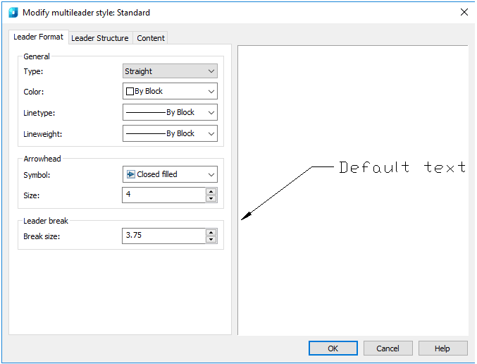
The Modify Multileader Style dialog box opens when you edit the current or create a new style.
In the left part the dialog contains three tabs with adjustable parameters, and in the right one – the preview area displaying the multileader in accordance with the current options.
Leader Format tab
Options:
General
|
Type |
Type of multileader line landing – straight, spline or no leader line. |
|
Color |
Drop-down list to select the multileader color. |
|
Linetype |
Drop-down list to select the typeline of the leader line. |
|
Lineweight |
Drop-down list to select the lineweight of the leader line. |
Arrowhead
|
Symbol |
The arrowhead symbol. |
|
Size |
The arrowhead size. |
Leader break
|
Break size |
Break size of the multileader. |
Leader Structure tab
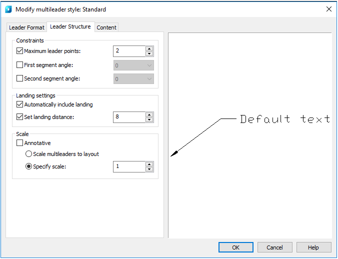
Options:
Constraints
|
Maximum leader points |
A leader point can have more than one segment and be similar to a jogged polyline. The option specifies the number of points for the leader line, which will be requested when constructing a multileader. |
|
First segment angle |
Specifies the angle of the first segment in the leader line. |
|
Second segment angle |
Specifies the angle of the second segment in the leader line. |
Landing settings
|
Automatically include landing |
Automatic addition of the landing when creating a multileader. If the option is disabled, the landing will not be added. |
|
Set landing distance |
Determines the fixed distance for the multileader landing line. |
Scale
|
Annotative |
Annotation of multileader. It is not used in the current program version. The option allows you to correct the object automatically for similar display in one and the same size or scale irrespective of the type scale. |
|
Scale multileaders to layout |
Scales the multileader in accordance with the current layout. |
|
Specify scale |
Specifies the scale of multileader. |
Content tab
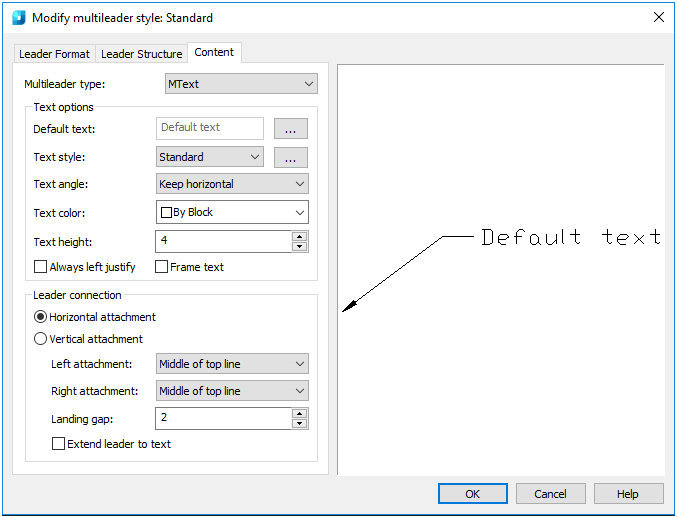
Options:
|
Multileader type |
Type of the multileader content: multiline text, attached block or no content. |
Text options
|
Default text |
Sets default text for the multileader. When creating a multileader it is possible to select: whether to leave the default text or enter the other one. |
|
Text style |
Predefined text style for the text. Displays the text styles downloaded as of the moment. |
|
Text line angle |
Specifies the rotation angle of the multileader text. |
|
Text color |
Specifies the color of the multileader text. |
|
Text height |
Specifies the height of the text. |
|
Always left justify |
Specifies that the text is left justified. |
|
Frame text |
Frames the text content of the multileader. |
Leader connection
|
Horizontal attachment |
Specifies the landing horizontal attachment to the content. |
|
Vertical attachment |
Specifies the vertical landing attachment to the content. |
|
Left/Top Attachment |
Specifies the method of left or top attachment (depending on the attachment option selected above). |
|
Right/Bottom Attachment |
Specifies the method of right or bottom attachment (depending on the attachment option selected above). |
|
Landing gap |
Specifies the distance between the content and the landing. |
|
Extend leader to text |
Available only in case of selecting the horizontal attachment. |