

-
-
-
-
-
-
-
-
-
-
-
-
-
-
-
-
-
-
-
-
-
-
-
-
-
-
-
-
-
-
-
-
-
-
-
-
Mesh Coloring by Height
-
-
-
-
-
-
-
-
-
-
-
-
-
Mesh Coloring by Height
 Ribbon: Topoplan – Texturing and Calculations >
  Mesh Coloring by Height
Menu: Ground – Textures >  Mesh Coloring by Height
Toolbar: Textures and Calculations > Mesh Coloring by Height
 Command line: NG_PAINT_ELEVATION
With this command you can create a textured surface with gradient paint. Sets the initial (color of minimum) and final (color of maximum).
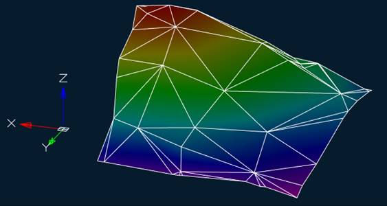
After running the command, specify the Mesh object in a drawing.
The command options are specified on the Properties toolbar.
Options:
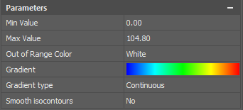
|
Min Value |
The minimum height value from which the surface will be painted. |
|
Max Value |
The maximum height value above which surface painting will not be performed. |
|
Out of Range Color |
The color of an uncolored surface if the minimum and maximum values are set to something other than the minimum and maximum elevation of the surface. · Black. · White. · Border – the color will correspond to the end color of the established gradient. |
|
Gradient |
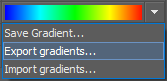
Gradient image of the future surface. A single click on the gradient opens a drop-down menu:
· Save Gradient – saves the gradient in the current document saves the gradient in the current document. · Export gradients – saves the gradient to an XML file. · Import gradients – imports the gradient from an XML file. A double click on the gradient image opens the gradient editor, discussed below. |
|
Gradient type |
Continuous – the surface will be painted with smoothly transitioning colors. Discrete – each color will be configured separately, the borders between colors are displayed with a clear line. When you select this option, you can specify the number of color intervals and adjust each color separately. |
|
Smooth isocontours |
Possibility to smooth the gradient edges. The parameter is reserved for the next version |
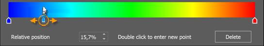
Double-clicking on the gradient image opens the gradient editor, where you can set your own colors and the location of the color transition points.
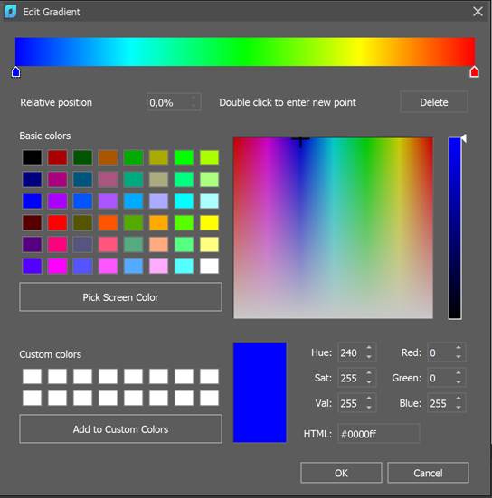
Initially, the gradient scale contains only two extreme points, for which you can set a new color by first clicking on any of them.
A new color transition point is set by a double click in the desired area of the gradient. A new point will appear at this location.
It is possible to:
· select a point by clicking on it (after creation, the point is selected automatically). In this case, the dialog displays its exact color and position;
· set a new point color using any color setting method in the dialog, including selecting a color from the screen. In this case, the coloring of the gradient scale will change in accordance with the new color of the point;
· specify a new location of the point on the gradient scale by moving it along the scale or by entering a relative position value. In this case, the coloring of the gradient scale will change in accordance with the new position of the point. The extreme points of the gradient scale cannot be moved;
· delete the point with the Delete button. The coloring of the gradient scale will change according to the remaining number and location of points. The extreme points of the gradient scale cannot be deleted.
Command prompt:
|
Apply changes <Yes> or [Yes/No]: |
Yes – the mesh will be painted with the current settings. No – if the settings have been changed, they are not saved. The mesh will be painted with the settings that were displayed immediately after running the command. |
To display the completed coloring, set the visual style to Realistic or X-Ray, or a custom style in which texture display is enabled in the face parameters.