

-
-
-
-
-
-
-
-
-
-
-
-
-
-
-
-
-
-
-
-
-
-
-
-
-
-
-
-
-
-
-
-
-
-
-
-
-
Internal PDF-Plotter
-
-
-
-
-
-
-
-
-
-
Internal PDF-Plotter
Internal PDF-Plotter
In the nanoCAD there is a possibility to transform and print the drawings to a PDF file (Adobe® Portable Document Format) by using the internal PDF-plotter. When printing, it is possible to create both several single-page PDF files and one multi-page file.
To print in PDF file:
1. Open the Plot dialog box.
2. In the drop-down list of the Printer/Plotter section select Internal PDF-plotter.
3. Click the Setup button.
4. Perform the necessary settings in the opened Internal PDF-plotter dialog box:
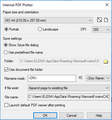
Options:
Paper size and orientation
|
|
Drop-down list to select paper formats. |
|
|
Edits the predefined paper format. Button to open the Modify paper format dialog box. |
|
|
Adds a new paper format. Button to open the Add paper format dialog box. |
|
Portrait |
Sets the portrait paper orientation. |
|
Landscape |
Sets the landscape paper orientation. |
|
DPI |
Sets the resolution to save in the PDF file. |


Save settings
|
Show save file dialog |
Opens the standard dialog box to specify the name and storage location of pdf-file after printing. |
|
Use predefined file name |
Turns on the mode of saving pdf-file with document file name (pdf-file name and its storage path are displayed in the File name field). |
|
Folder: |
Displays the path to the folder of pdf-file storage. By default, it sets the folder that contains the original document. It is possible to select another folder for storing pdf-file by turning off Use the document file folder checkbox and clicking |
|
Use document file folder |
Turns on the mode of the pdf-file storage in the original document folder. |
|
Filename mask: |
Sets the template for the pdf-file name. To the pdf-file name entered in this field, the name of original document, layout name, user name, etc. separated from file name and from each other with underscore symbol (_) can be added automatically with help of variables. |
|
|
Drop-down list of variables to form the pdf-file name template. The following variables are available: · <Doc name> – The <DN> variable adds the name of the original document to the name of created pdf-file. · <Layout name> – The <LN> variable adds the layout name of the original document to the name of created pdf-file. · <User name> – The <UN> variable adds the user name to the name of created pdf-file. · <Time> – The <T> variable adds the time of file creation to the name of created pdf-file. · <Date> – The <D> variable adds the date of file creation to the name of created pdf-file. · <Counter1> – The <C1> variable adds the number (index) in the format of 1, 2, 3, etc. to the name of created pdf-file. · <Counter01> – The <C2> variable adds the number (index) in the format 01, 02, 03, etc. to the name of created pdf-file. · <Counter001> – The <C3> variable adds the number (index) in the format 001, 002, 003, etc. to the name of created pdf-file. · <Counter0001> – The <C4> variable adds the number (index) in the format 0001, 0002, 0003, etc. to the name of created pdf-file. · <Counter00001> – The <C5> variable adds the number (index) in the format 00001, 00002, 00003, etc. to the name of created pdf-file. · <Counter000001> – The <C6> variable adds the number (index) in the format 000001, 000002, 000003, etc. to the name of created pdf-file. · <Separator> – The <_> variable adds the underscore symbol (_) to the name of created pdf-file. All variables, when added to the existing file name template, are automatically separated with underscore symbol (_). If necessary, the underscore symbol (separator) can be inserted in the template manually by selecting in the drop-down list. |
|
If file exists: |
Drop-down list to set options, when saving pdf-file with the name of already existing file. The following parameters are available: · Append page to existing file – Appends the PDF pages of the document to the pages of already existing pdf-file. · Show warning dialog – When setting this option, after clicking Plot button, the Specify action dialog box opens: The dialog box proposes the user to choose options to save pdf-file: · overwrite the existing file (the Overwrite button); · save in a new file with the name of an existing file, to which the number will be added automatically (the Autonumbering button); · add the document pages to the pages of an existing pdf-file (the Add page button). · Always overwrite existing file – Overwrites the contents of an existing pdf-file. · Auto numbering file name – Saves a file with new name consisting of the name of an existing file and automatically added number (index). |
|
File name: |
Displays the path and specified name of the pdf-file. |
|
Launch default PDF viewer after printing |
Turns on/off the viewing in the installed software of PDF files viewing after the end of pdf-file printout. |
|
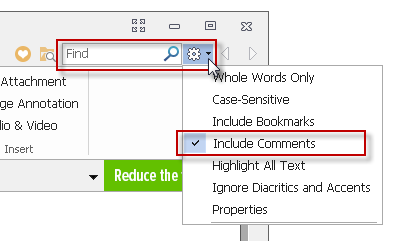
SHX text annotations |
When printing to PDF, it is possible to convert SHX texts to PDF comments. Such comments will be created at the locations of text objects with the SHX font. Comments contain the full text of these objects. This allows you to search the contents of SHX text in a PDF document. To search for text in PDF comments, you need to activate the Include comments option in the Search settings of PDF viewer.
Comment creation can be disabled by the PDFSHX variable or with the SHX text annotations check box. |
 button.
5. Click OK to close the Internal PDF-printer dialog.
6. Set the necessary parameters in the Plot dialog box: specify plot area, plot scale, etc.
7. To printout the document to PDF file, click the Plot button.