

-
-
-
-
-
-
-
-
-
-
-
-
-
-
-
-
-
-
-
-
-
-
-
-
-
-
-
-
-
-
-
-
-
-
Insert .dwg Table
-
-
-
-
-
-
-
-
-
-
-
-
-
-
-
-
-
-
-
-
-
-
Insert .dwg Table
.dwg Tables
Inserting .dwg Tables
 Ribbon: Annotate – Tables –
  .dwg Table
Menu: Draw – Tables >  Tables .dwg…
 Toolbar: Draw –
 Toolbar: Tables –
 Command line: DTABLE
Inserting an empty table into a drawing.
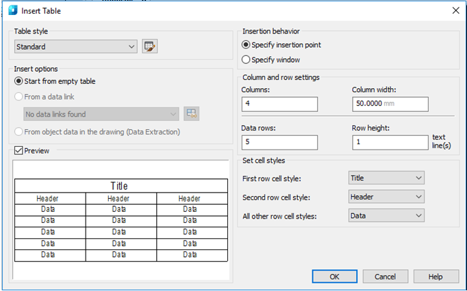
Parameters:
Table style
In the current drawing select the table style based on which it is required to create a table. You can create a new table style by clicking the button next to the drop-down list.
Insert options
Specifies the way to insert a table.
|
Start from empty table |
Creates an empty table that can be filled with data manually. |
Preview
Manages the display of preview sample. If the table is empty, the sample is the example of the table style. When connected with the table, the sample corresponds to the obtained table. When working with large tables to increase the performance, the checkbox can be deselected.
Insertion behavior
Specifying a table location.
|
Specify insertion point |
Specifies the location of the left upper corner of the table. It is possible to use picking device or enter coordinates in the command line. If the table style determines the table construction direction from bottom up, the insertion point corresponds to the left lower corner of the table. |
|
Specify window |
Specifies size and location of the table. You can use picking device or enter coordinates in the command line. When selecting this option the number of columns and rows, as well as column width and row height depend on the frame size, as well as on column and row settings. |
Column and row settings
Specifies the number of size of columns and rows.
|
Columns |
Specifies the number of columns. When selecting Specify window option and setting column width, the Auto parameter is enabled and the number of columns is calculated in accordance with the table width. If the table style containing the original table is specified, it is possible to select the number of additional columns to be added to this original table. |
|
Column width |
Specifies the column width in the table. When selecting Specify window option and setting the number of columns, the Auto parameter is enabled and the column width is calculated in accordance with the table width. The minimum column width is one printed character. |
|
Data rows |
Specifies the number of rows. When selecting Specify window option and setting row height, the Auto parameter is enabled and the number of rows is calculated in accordance with the table height. Table style with a title row and a header row determines the table containing at least three rows. The minimum row height is equal to one text line. If the table style containing the original table is specified, it is possible to select the number of additional data rows to be added to this original table. |
|
Row height |
Specifies the row height in the text lines. Text line height depends on the text height and space from cell borders; these parameters are set in the table style. When selecting Specify window option and setting the number of rows, the Auto parameter is enabled and the row height is calculated in accordance with the table height. |
Setting cell styles
Applies to styles of tables not containing the original table; determines cell style for rows of the new table.
|
First row cell style |
Determines cell style for the first row in the table. By default, the Name cell style is applied. |
|
Second row cell style |
Determines cell style for the second row in the table. By default, the Column cell style is applied. |
|
All other row cell styles |
Determines cell style for all other row in the table. By default, the Data cell style is applied. |