

-
-
-
-
-
-
-
-
-
-
-
-
-
-
-
-
-
-
-
-
-
-
-
-
-
-
-
-
-
-
-
-
Import of Point Clouds
-
-
-
-
-
-
-
-
-
-
-
-
-
-
Import of Point Clouds
 Ribbon: Point Clouds > Point Cloud >
  Import
Menu: Insert >  Point cloud
Menu: Point clouds > Import
Toolbar: Point cloud >
 Command line: NPC_IMPORT
Inserts point clouds to the current drawing from LAS, LAZ, BIN, PTX, PTS, PCD, TXT, XYZ, XYB, PLY, E57, RCS, RCP, NPC files. File formats are described in more detail in the Point Cloud Data Formats section.
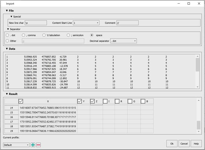
When importing point clouds from text files (TXT, XYZ, XYB), a separate import wizard dialog is displayed. It allows you to set the data interpretation rules for the imported file.
Options:
Special
Specifies the next line character, the line from which data starts and the characters that are interpreted as the start of a line with comments.
Separator
Specifies character that separates text file data. You can choose both predefined character (semicolon, tab character, comma, space), and set any other one.
|
Consider consequent separators one |
Specify a character used to separate whole and fractional parts of values |
|
|
|
Data
Preview of text file data.
Result
Specify correspondence of text file columns to certain data types: point coordinates by X, by Y and by Z, intensity value, point color in RGB (red, green, blue).
The Data field displays 100 lines from the file, and the Result field displays 50.
Changing the Content Start Line value will display the next 50 lines.
After Text Files Import Wizard is closed, the main point clouds Import dialog box opens.
Point Clouds Import Dialog Box
The Import dialog box allows you to specify what data to import and how. It gives visual representation of the file’s point cloud and get understanding of the data in the file.
The dialog that opens shows base parameters and visual representation of point clouds in imported file.
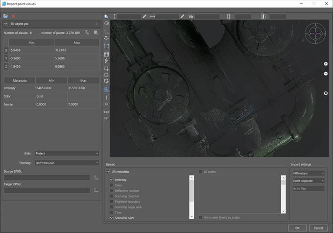
The import dialog allows you to:
· import several files at the same time;
· view detailed information about each file and its metadata values;
· set an individual point cloud transformation from each file using EPSG codes (if the point cloud has a coordinate system described by the EPSG code, or the user sets EPSG for it manually);
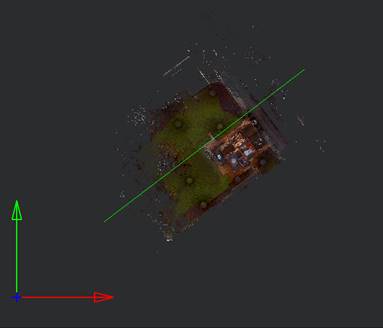
· organize a preview of a point cloud in 3D, as well as to select a spatial fragment in any perspective selected by the user;
· set units of measurement for source data, as well as manage drawing units and data conversion from source units to drawing units;
· specify the types of metadata to be imported from source data;
· specify the classes to be imported from the source data;
· set data thinning during import;
· set partition into clouds by classes, sources, echoes;
· split point clouds into blocks, both along the grid and along the flight line. In this case, the cloud is not loaded immediately into the drawing. A set of dwg files is created in the folder with the point cloud, each of which contains a block - a fragment of the cloud, obtained by splitting the source file in accordance with the specified parameters. The function is convenient to use to automate import, the resulting fragments can be loaded into the drawing separately, significantly reducing the amount of memory used;
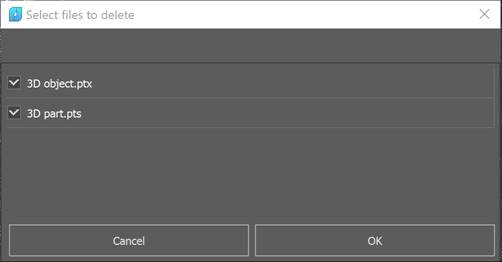
· remove files from the downloaded list.
Options:
Selected file
Displays the path to imported file.
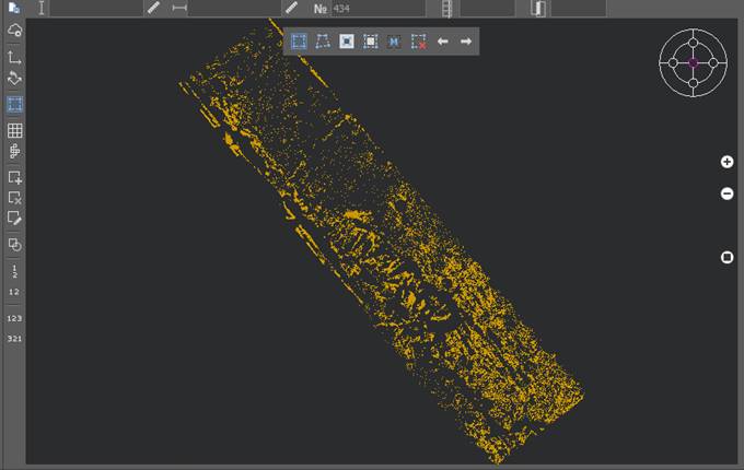
Preview
Preview displays all contents of the imported file. You can specify areas to import. By default, all points will be imported, However it is possible to specify one or more areas of diverse geometry instead of loading all file points. To select areas, you must activate the set of area selection tools:
|
|
Specifies a rectangular area whose points will be imported into the document. Several such areas may be defined. |
|
|
Specifies the polygon area whose points will be imported into the document. To stop specifying the area, right-click the mouse. Several such areas may be defined. |
|
|
The tool allows you to invert the selected areas. |
|
|
Select the entire contents of the file being imported. |
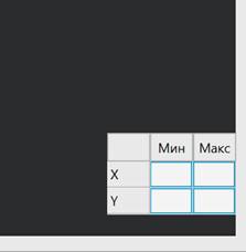
|
|
Manually specifying the coordinates of the area whose points will be imported into the document. The button opens a dialog box, in the fields of which the coordinates of the full scan boundaries are indicated. To create an area in this case, the coordinates of the desired area are indicated in the fields.
Several such areas may be defined. |
|
Reset selection |
Allows you to completely remove all previously selected areas. |
|
UNDO, REDO selection |
It is possible to undo and redo operations for creating selection areas. |
|
|
View locator, similar to that in the main window. Allows you to select standard views. |
|
|
Enlarges, reduces, or displays the entire image in the preview window. |
|
Show all files
|
Upon clamping, it turns on the mode of displaying the data of all files in the preview window. When unclamped, the mode of displaying only the data of the currently selected file works. |
|
On/Off project mode |
When unclamped, it activates the mode of importing into the current document. When clamped, it activates the project work mode. In this mode it is possible to split the resulting data set into blocks, create a project file, as well as a project mosaic drawing. |
|
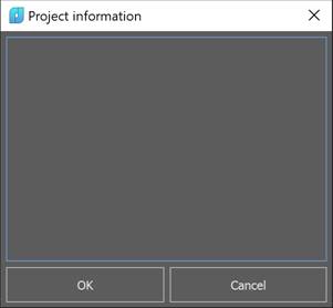
Edit project information |
Clicking this button opens the project description editing window. Only available in the project creation mode
|
|
Show axis |
When clicked, activates the display of the project CS axes. Only available in the project creation mode
|
|
Rotate axis |
Tool for setting a project coordinate system. Only available in the project creation mode
|
|
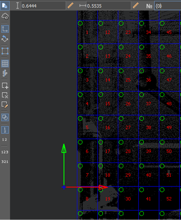
On/Off grid of blocks |
Only available in the project creation mode Specifies the size of blocks and their numbering mode
It is possible to measure distances in the preview window
The result of this mode is the creation of a split grid
|
|
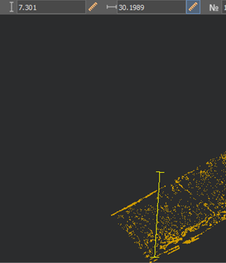
On/Off blocks by flight line |
Only available in the project creation mode Specifies the size of blocks and their numbering mode
Next comes the flight line selection
|
|
Add block |
Only available in the project creation mode Works only in flightline splitting mode. Allows you to create a new block where the user specifies. |
|
Remove block |
Only available in the project creation mode Works only in flightline splitting mode. Allows you to delete an existing block. |
|
Edit block |
Only available in the project creation mode Works in both splitting modes (grid and flightline). Allows you to change the block name manually. |
|
Show all files |
On – Sjows all files. Off – Shows only the last one |
|
Switching block numbering |
Enables vertical numbering; Enables horizontal numbering; Enables start to end numbering; Enables end to start numbering. |


 (to automatically generate a number, you need to use round brackets in which to place the starting number),
  number of blocks perpendicular to line and
  overlap width of blocks:


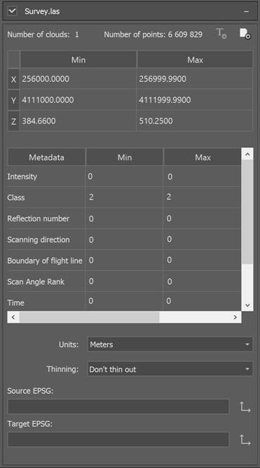
File Information
This section displays statistics on the points of the imported file. You can set the units of the cloud, its coordinate system, and adjust thinning.
It is possible to reduce the density of imported clouds, in case of its redundancy, by importing every second/third/tenth, etc. file points. To do this, check the Interval box and specify the sequence number of the imported point in the Import each <…> field.
Using the checkbox in the left corner of the panel, you can include this file in the import data set or exclude it. For text files, there is a format setting button in the upper right corner (a description of the text file import settings window can be found in the Text File Import Wizard).
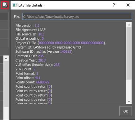
Detailed file information
Further in the right corner there is a button for obtaining detailed information about a LAS or LAZ file, you can view the properties in a text dialog.
Convert to
Setting up coordinate systems works as follows. If the file does not have a georeference, then it can be selected manually.
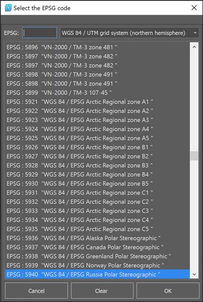
Having selected the desired coordinate system, we proceed to specify the target coordinate system in the same way.
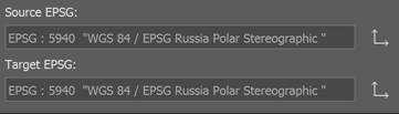
If the file has a georeference written to the file itself, then you do not need to select the source coordinate system, it will be automatically filled in when opening the file.
When importing multiple files, the target coordinate system cannot be set differently for different files. Changing the target coordinate system for at least one file will automatically change it for all.
Besides, if there are several source files and they have different source coordinate systems, when you click OK, a message appears asking for the same source coordinate systems or to set them to a target coordinate system.
Filter by metadata
This list contains all metadata (attributes) of points present in the file.
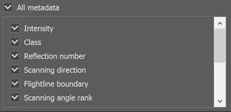
After import, the points will have only the attributes selected in this list. Unselected attributes will not be included in the document.
Filter by code
This list contains all the classes to which the points of the imported file have been distributed. If the cloud points had no classes, the list will be empty.
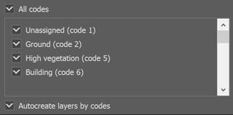
Only those points that belong to the classes selected in this list will be imported. Points of the classes that were not selected will not be included in the document.
Creates layers with names of classes. Layers named according to LAS standard classification. Each layer get the FC#N description, where: FC# - index number, N – class number.
If the Auto fill code layers checkbox is off, then a single layer Point Cloud will be created during the import. The description field of this layer could be filled manually.
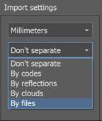
Differentiation
By default, file points are imported into the document as a single cloud. However, it is possible to import points as multiple clouds. The division of points into clouds can be carried out according to various criteria.
|
Don’t separate |
Import one cloud regardless of the cloud number in imported file. |
|
|
By codes |
Import points as separate clouds. Each cloud contains points with its code and one cloud with unclassified points. |
|
|
By reflections |
Each cloud contains points with its value reflection. |
|
|
By clouds |
Divide points on the number of clouds in file. |
|
|
By files |
In the By files separation mode, cloud objects (both entire clouds and their parts located in external constraints) have the same names as the files from which they were loaded. |
|
Note: Special option hides separate points to avoid nanoCAD braking. This option is enabled by default. Turn on Display all points in Point clouds – Settings menu to display all points of cloud. It is also not recommended to open files from the Desktop in Windows. Point clouds with more than 2.4 billion points are not supported. To be able to work with the data, you should split the point cloud into smaller parts using our import tools.