

-
-
-
-
-
-
-
-
-
-
-
-
-
-
-
-
-
-
-
-
-
-
-
-
-
Image Adjust
-
-
-
-
-
-
-
-
-
-
-
-
-
-
-
-
-
-
-
-
-
-
-
-
-
-
-
-
-
-
Image Adjust
Displaying quality of raster images
The commands in this section adjust the display of raster images on the screen without modifying their raster data. Changes made by these commands will not in any way affect the display of the same images in another document or another program.
 Ribbon: Raster – Settings >
  Image Adjust
Menu: Raster –  Image Adjust
 Toolbar: Modify Object –
 Command line: IMAGEADJUST, IAD
You can adjust the brightness, contrast and fade for the display of the raster image without affecting the original raster image file. The image adjustment is intended for improvement of the display of raster images (adjust contrast to make poor-quality images easier to read) or special effects.
note: To change the intrinsic brightness, contrast, hue and saturation of raster images, use the  Brightness/Contrast (LEVELS) command. This command, unlike the Adjust Raster command, modifies the raster image data.
Bitonal images cannot be adjusted for brightness, contrast or fade.
Raster image is selected by its contour (frame or clip border).
To adjust raster image options, use the Image Adjust dialog box.
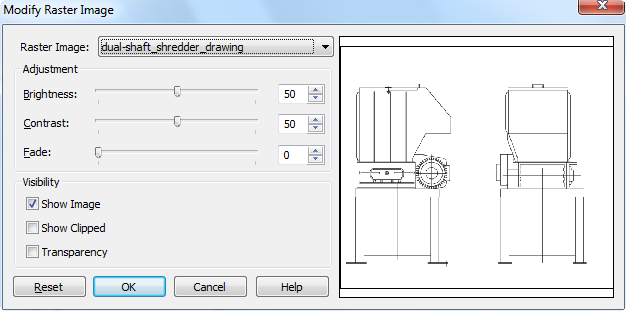
Parameters:
|
Raster Image: |
List of the raster images inserted in the drawing. |
|
|
Adjustment |
||
|
Brightness: |
Controls the brightness of the raster image display. |
|
|
Contrast: |
Controls the contrast of the raster image display. |
|
|
Fade: |
Controls the fading effect of the raster image display.
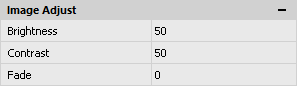
These parameters are also available in the Image Adjust section of the Properties functional bar:
|
|
|
Visibility |
||
|
Show Image |
Controls the display of the image content on the screen. If this checkbox is not selected, then only the contour of the raster image is shown. |
|
|
Show Clipped |
If this checkbox is selected, only the clipped area of the raster image is displayed. Otherwise, the raster image is displayed completely, even if a clip has been set for it. To set a clip for the raster image use the Image Clip command (ribbon > Insert tab > Reference > Hatch > Image Clip). |
|
|
Transparency |
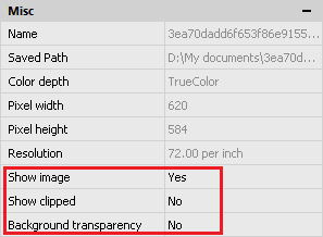
Used only for bitonal raster images and images with transparent pixels. Makes the background color of the image transparent. When enabling the transparency mode, it becomes possible to view through transparent pixels of the raster image of objects that are in the graphics area behind the raster. The transparency property is supported for those raster file formats in which transparent pixels exist, for example, in monochrome images (* .BMP) background pixels are transparent. These parameters are also available in the Misc section of the Properties functional bar:
|
|
|
|
Resets the values for brightness, contrast and fade to the default settings. |
|

You can set transparency level for the raster image as for drawing object.
To change the transparency of the raster image as drawing object:
1. Select the raster image.
2. Select a transparency value in the Transparency drop-down box in the General section of the Properties panel.
The IMAGEFRAME system variable allows you to manage the visibility of the clipping contour and raster contour. If the system variable is set to value 1 (set by default), the contour is displayed on the screen and you can select it and print it. If system variable is set to value 0, the contour visibility is turned off and you cannot select it and print it. If system variable is set to value 2, the contour is displayed on the screen, but you cannot print it.
There are commands in the Raster menu – Object > Image > to make work with IMAGEFRAME system variable easier:
Frame On - Sets IMAGEFRAME = 1
Frame Off - Sets IMAGEFRAME = 0
Print Off - Sets IMAGEFRAME = 2