

-
-
-
-
-
-
-
-
-
-
-
-
-
-
-
-
-
-
-
-
-
-
-
-
-
-
-
-
-
-
-
-
-
Editing Tables on the Drawing
-
-
-
-
-
-
-
-
-
-
-
-
-
-
-
-
-
-
-
-
-
-
Editing Tables on the Drawing
The on-screen table editor is opened by starting the In-place edit (ipedit) command or left-clicking the table frame while holding down the CTRL key.
To enter the content of a cell:
1. Place the cursor above the cell.
2. Left-click.
The active cell is then highlighted in green. The text entered in a cell is automatically condensed to fit the cell width.
The Table Edit toolbar is shown when a table is being edited on-screen.
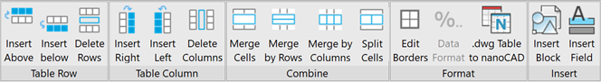
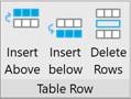
Table Row Group
|
Insert above |
Adds one line at the position where the selected cell is located. |
|
Insert below |
Adding one row at the bottom of the table. |
|
Delete Rows |
Deletes the row that contains the selected cell. |
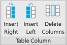
Table Column Group
|
Insert Right |
Adds one column to the table on the right. |
|
Insert Left |
Adds one column to the table on the left. |
|
Delete Columns |
Deletes the column that contains the selected cell. |
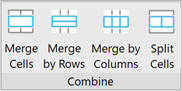
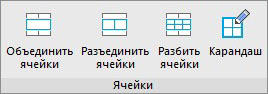
Combine Group
|
Merge (Merge by Rows) (Merge by Columns) |
Merges adjacent cells into one: · Place the cursor over the cell that needs to be merged with other adjacent cells (the cell is highlighted in green). · Confirm the cell selection by clicking the left mouse button. · Move the cursor to the last cell to be merged (adjacent cells to be merged are also highlighted in green). · Confirm the selection of the last cell by clicking the left mouse button. |
|
Split |
Splits previously merged cells: · Place the cursor on a cell that was previously combined from several cells (the cell is highlighted in green). · Confirm the cell selection by clicking the left mouse button. · Left-click again to split the cell into its initial cells. |
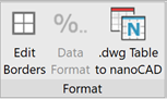
Format Group
|
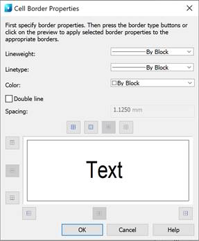
Edit borders |
Modifies the properties of the table borders of one or more cells using the Cell Border Properties dialog box:
· First specify border properties. · Then press the border type buttons or click on the preview to apply selected border properties to the appropriate borders. |
|
.dwg Table to nanoCAD |
Converts .dwg table to nanoCAD (CONVERTTABLEA command). |
In the classic interface the Edit .dwg Table toolbar opens:
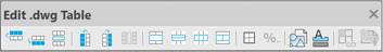
Buttons:
|
above |
Adds one line at the position where the selected cell is located. |
|
|
Adds one row at the bottom of the table. |
|
|
Deletes the row that contains the selected cell. |
|
|
Adds one column to the table on the left. |
|
|
Adds one column to the table on the right. |
|
|
Deletes the column that contains the selected cell. |
|
|
Merges adjacent cells into one. |
|
by Rows) |
Merges two or more cells in a row. |
|
Columns) |
Merges two or more cells in a column. |
|
|
Splits previously merged cells. |
|
|
Modifies the properties of the table borders. |
|
|
Inserts a block. |
|
|
Inserts a field. |


