

-
-
-
-
-
-
-
-
-
-
-
-
-
-
-
-
-
-
-
Drawing Explorer
-
-
-
-
-
-
-
-
-
-
-
-
-
-
-
-
-
-
-
-
-
-
-
-
-
-
-
-
-
Drawing Explorer
 Ribbon: Manage – Palettes >
  Drawing Tree
Menu: Modify –  Drawing Explorer
Menu: View – Toolbars > Functional > Drawing Explorer
Toolbar: Properties –
 Command line: DRAWINGEXPLORER
|
|
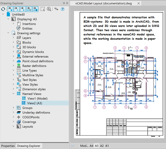
Drawing Explorer provides full information about all objects in drawing: · graphic objects; · block references, external references, raster images; · parameters of drawing settings. All changes in drawing reflect in Drawing Explorer immediately. You can separately get the information in Explorer (and also in a drawing area) about new objects and about objects changed since last saving. You can open dialogs for editing parameters and properties of objects directly from Drawing Explorer.
|
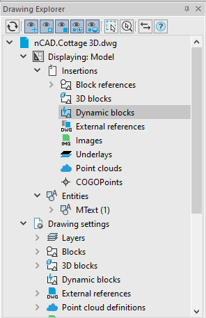
The name of the current document is displayed in the root section of the dialog hierarchical structure. Which, in turn, contains two subsections: Displayed and Drawing Settings.
Objects in the current document space
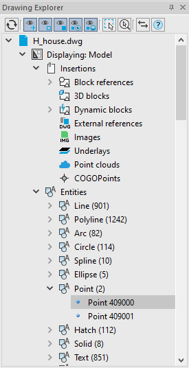
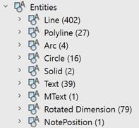
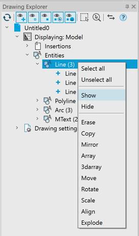
The Displayed section contains a hierarchical list of all occurrences and objects in the current document space — model space or paper space. Objects are grouped by type. The number of objects of this type in the current document space is given in parentheses.
|
|
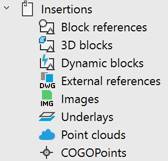
The Insertions subsection displays all Insertions of the current model or paper space: regular, dynamic, and 3D block inserts, xrefs, raster images, underlays, and point clouds. The Entities subsection displays objects in the current space grouped by type. If geopoints were imported to the file, a separate section will appear.
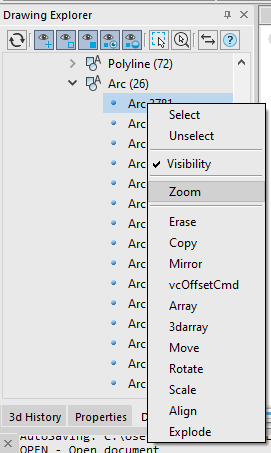
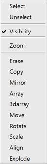
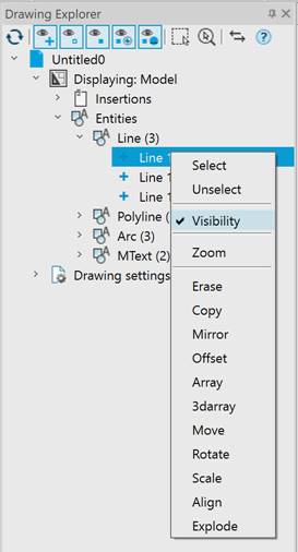
The context menu of drawing objects selected in the dialog structure contains commands for managing objects. The list of available actions depends on the type of object or group of objects. You can select objects in the drawing, pan, apply editing commands, turn display on and off in the drawing, delete. |
Thus, for example, you can hide or make visible both an individual object and a group of objects. To make a previously hidden object visible on the screen again, select the Visibility item. For a group of objects - the Show item.
|
|
|

Tools for control of displaying objects
At the top of the drawing explorer, there are buttons to control the display of objects in the explorer tree and in the drawing field. Initially, the tree of the drawing explorer contains a list of all objects:
|
|
Refresh tree |
Renew information. All opened sections will be closed. |

Filters of displaying objects in the Explorer tree:
|
|
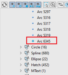
Show created objects |
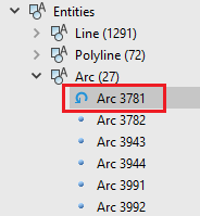
Displays information about new objects in the current session of the drawing. In the Drawing Explorer such objects have a “plus” sign.
|
|
|
Show modified objects |
Displays information about objects changed in the current session of the drawing. In the Drawing Explorer such objects have a “load” sign.
|
|
|
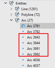
Show resident objects |
Displays information about unchanged objects of the drawing. In the Drawing Explorer such objects have a “point” sign.
|
|
|
Show visible objects |
Displays objects visible in the drawing in the Explorer. |
|
|
Show hidden objects |
Displays objects invisible in the drawing in the Explorer. |


Variants of displaying on the screen
|
|
Enable selection |
Objects selected in Explorer tree marks with grips in a drawing area. |
|
|
Enable zoom and selection |
Objects selected in Explorer tree marks with grips and places in the center of drawing area. |
|
|
Synchronize filters with drawings |
Displays objects in a drawing area according to status of filters. · · · You can display objects hidden in the drawing field back by disabling one of these filters. |


 Show new objects
 Show modified objects
 Show resident objects
Objects of the Current Document Space
The Displaying section contains a hierarchical list of all insertions and entities of the current document space – model or paper space. The number of insertions and entities in the current document space is given in parentheses.
|
|
The |
|
|
The Proxy objects (with and without graphical representation) are displayed with the Annotative objects have the
|


 sign.
sign. sign:
sign:
The context menu of insertions and drawing entities selected in the dialog structure contains object management commands. The list of available actions depends on the type of object or group of objects. You can select objects in the drawing, pan, apply editing commands, turn on and off display in the drawing, and delete.
Thus, for example, the following context menu commands are available for Insertions – Point Clouds:
The Explode the Cloud into Points (NG_EXPLODE_POINTCLOUD) command appears if you have a license for the Topoplan module.
Also, using the context menu, you can hide or make visible both an individual object and a group of objects. To make a previously hidden object visible again on the screen, select the Visibility item. For a group of objects – the Show item.
|
|
|
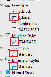
The Drawing Settings section displays the list of named objects of a drawing: layers, blocks, xrefs, etc. grouped by object type.
|
Objects of different types have a context menu with own set of actions.
Usually, an element can be made current in a document, deleted, renamed.
A double-click on a named object sets it current in the document. Pictograms of current objects are marked with a colored dot.
|
|
note: Please, remember that when you set the selected sheet current, there will be a transition to this paper space with automatic update of the entire contents of the drawing explorer.
The context menu of the Layers group opens the Layers dialog:
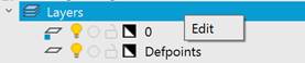
You can enable/disable, freeze/unfreeze and lock/unlock a layer in the Drawing Explorer by clicking on the corresponding icon while holding down the CTRL key. Changes will be immediately reflected in the drawing. Double clicking on a layer sets it as current.
Layers present on xrefs have the  icon.
icon.
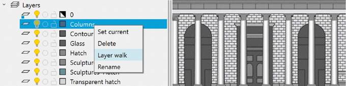
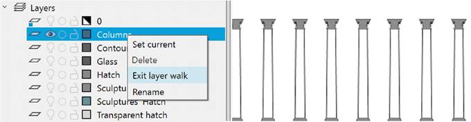
In the context menu of layers, you can turn on the layer walk mode. In this mode, only the objects of the layer currently selected in the manager will be displayed in the drawing field. Exit from the layer walk mode is also performed through the context menu of layers.
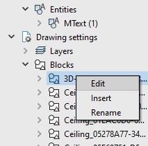
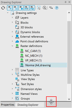
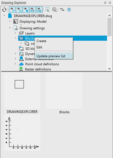
For Blocks, 3D Blocks, Dynamic blocks, and Rasters, you can open a preview in the Drawing Explorer (hidden by default). To do this, move the cursor over the bottom border of the bar and expand the preview area:
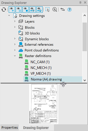
When you double-click on a block (raster) preview, the Insert Block (Insert Raster) dialog box opens.
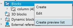
In order to create a preview of a group, select the Create preview list command in the context menu of Blocks, 3D blocks or Dynamic blocks:
When changing blocks, to update the display, select the Update preview list command in the context menu:
You can adjust the preview size and scale in the .ini file. The default size is 96x96, scale 1:1.
The context menu of the External References group allows you to:
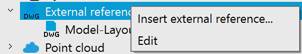
· Insert external reference… (XATTACH) by specifying the .dwg file;
· Edit… – reinsert references already existing in the drawing using the Drawing Explorer... toolbar (EXTERNALREFERENCES):
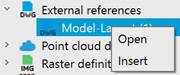
The external reference context menu allows you to open a file via the link in a separate tab or open the Insert external reference window to edit the insertion parameters:
To manage named views, the context menu of the Named Views group allows you to Create or Edit existing named views (VIEW, -VIEW command):
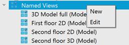
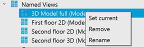
The named view's context menu allows you to Set current, Remove and Rename a view:
You can also set a view by double-clicking on a named view, which will auto-pan the view and display its boundaries with a red frame:
Work with Groups is described in the Using Drawing Explorer Bar to Work with Groups section.
Work with Geopoints is described in the Geopoints in the Drawing Explorer section.