-
-
-
-
-
-
-
-
-
-
-
-
-
-
-
-
-
-
-
-
-
-
-
-
-
-
-
-
-
Dimensions Editing
-
-
-
-
-
-
-
-
-
-
-
-
-
-
-
-
-
-
-
-
-
-
-
-
-
-
-
Dimensions Editing
The Edit dimension dialog box (if Yes is chosen for the Dimensions option of the Settings nanoCAD Int dialog box on the Main options tab of the Editing - By double-click section (the Tools menu –Advanced Settings)) can be opened:
· by double-clicking on the dimension,
· by right button clicking with CTRL pressed on the dimension,
· by moving the cursor over the dimension and clicking the right button,
The edit and fedit commands allow you to open the Edit dimension dialog box, it does not matter whether Yes is set or not.
You can also open the Edit dimension dialog box:
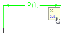
· by placing the cursor over the dimension and selecting Edit in the tooltip:
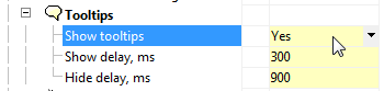
Note: To invoke the dialog this way you should choose Yes for the Show tooltips option (the nanoCAD – Options dialog box – the Main option tab – the Tooltips section):
· Select dimension, press the right button and select the Edit command in the context menu.
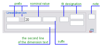
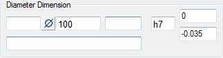
The Edit dimension dialog box:
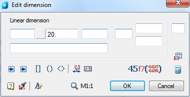
The structure of the input fields for the dimension text:
Options:
|
Dimension type: |
In this section the dimension type (for example, Linear dimension, Diameter dimension, Angular dimension etc.) and values of the dimension text are displayed. |
|
Prefix: |
The prefix consists of the text input field and the Symbol button. If the dimension does not have a special symbol that is set as the default prefix, the button is displayed without an image:
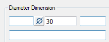
If a special symbol from the panel is set by default, it appears on the button:
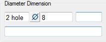
A prefix specified in the Edit dimension dialog box has precedence over a prefix set by default. Example of dimension text with a prefix consisting of the text and special symbol:
|
|
Nominal value: |
Field to display and edit the nominal value of the dimension text. |
|
Suffix: |
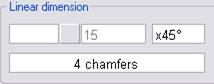
This field displays the suffix of the dimension text set by default, such as the chamfer angle designation:
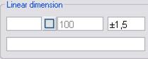
In the same field, you can set the value of a custom symmetrical fit of the dimension:
|
|
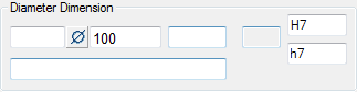
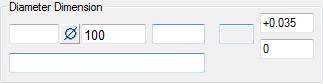
Fit designation: |
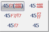
The fields display the specified fit values of the dimension. Depending on the way the fits are written (the Fit view button), the values in the fields can be displayed in different ways:
|
|
Note: |
The input field for a note for the dimension is used to create the hyperlink to the item that contains the technical conditions that define the general requirements for several dimensions. For example, in this field you can type the star symbol (*) to denote the reference dimension (having the corresponding item in the technical conditions). |
|
The second line of the dimension text: |
An example displaying the dimension text consisting of two lines:
|
 . Click the icon to open the panel to select a symbol:
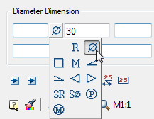
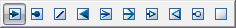
Buttons
|
|
These buttons are used to change the arrow type. Click to open the panel and select the required arrow type:
|
|
|
These buttons are used to turn on/off the modes for placing text in the Square, Round or Pointed brackets. |
|
|
This button is used to turn on/off the mode for placing the text on the leader. Example: Mode is on Mode is off
|
|
|
This button is used to turn on/off the mode for placing the text in a rectangle. |
|
|
Use this button to choose the method of writing the fit. Click to open the following panel:
|
|
|
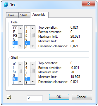
Opens the Fits dialog box. |
|
|
Opens the Calculator. |
|
|
This button opens the Text settings dialog box to change the style, height and color of the dimension text. |
|
|
The Match Properties button temporarily closes the Edit dimension dialog box to select the dimension whose properties should be copied to the editable dimension. |


The Text Settings dialog box:
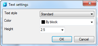
Options:
|
Text style |
The drop-down list to select the text style. |
|
Color |
The drop-down list to select the text color. |
|
Height |
The drop-down list to select the height of the symbols. It is possible to type the values from the keyboard. |
Please note that context menus, which include the following commands, are available in the input fields of the dimension text:
|
|
These commands are used to collect inputted information and insert it into the input fields if necessary. |
|
|
The functions of the first three commands of this section are as their names suggest. The Pick from drawing command temporarily closes the Edit dimension dialog box and opens the Value picker dialog box to get different objects properties from the drawing. You can then insert them into the Edit dimension dialog box. |
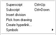
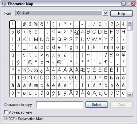
The Symbols command allows you to insert various symbols into the input fields, including characters from the Windows table:
|
|
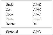
The commands from this section allow you to perform operations using the clipboard. |
|
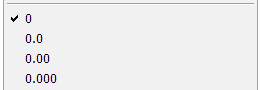
|
Sets the precision of the nominal dimension. |
To set the dimension fit:
1. Click the button  .
.
2. In the panel that appears, select the method of writing the tolerances:
3. Click the button  .
.
4. In the opened Fits dialog box, select the required values: