

-
-
-
-
-
-
-
-
-
-
-
-
-
-
-
-
-
-
-
-
-
-
-
-
-
-
-
-
Dimensioning
-
-
-
-
-
-
-
-
-
-
-
-
-
-
-
-
-
-
-
-
-
-
-
-
-
-
-
-
Dimensioning
Dimensions display the geometrical attributes of the objects on the drawing, as well as the distances and angles between them. The dimensions are part and parcel of any drawing.
In general, dimensions can consist of the following items:
· The dimension line indicates the direction and extent of a dimension. For angular dimensions, the dimension line is an arc.
· The extension line is drawn from the measured object to the dimension line.
· Arrows are displayed at the ends of the dimension line. You can use different types of arrows, including tick marks and points.
· The dimension text displays the numerical value of the measured object. The text can also include prefixes and suffixes, for example, symbols of the radius, diameter, degree, etc., as well as tolerances.
· The leader is the line joining together the dimension text and the dimension line to which it belongs. Leaders can be created automatically (when the corresponding options are set), when the text size does not fit between the extension lines or when you manually drag the dimension text (with grips) to another place.
The four basic types of dimensioning are:
· Linear dimensions display the distance between the specified points. This type includes the following dimensions:
· horizontal,
· vertical,
· aligned,
· ordinate,
· group dimension,
· base dimension and
· dimensions chain.
· Radial dimensions indicate the radii and diameters of arcs and circles. These include:
· diameter,
· radius,
· big radius.
· Angular dimensions are used to indicate the angles between two segments or three points.
· Arc dimensions display the length of an arc or an arc segment of a polyline.
Dimensions can be associative, non-associative or exploded. Associative dimensions adjust to changes in the geometric objects that they measure.
· Associative dimensions. Automatically adjust their locations, orientations and measurement values when the geometric objects associated with them are modified.
· Non-associative dimensions. Selected and modified with the geometry they measure. Non-associative dimensions do not change when the geometric objects they measure are modified.
· Exploded dimensions. Contain a collection of separate objects: lines, arrows, arcs and text, rather than a single dimension object. Exploded dimensions do not change when the geometric objects they measure are modified.
To manage the associativity of dimensions, use the Set associativity during insertion of objects option of the Settings nanoCAD Int dialog box on the Main options tab of the Edit section (the Tools menu – Advanced Settings)). The option has two values: Yes – for associative dimensions and No - for non-associative dimensions. To get the exploded dimensions, you should use the Explode command from the Modify menu.
note! In nanoCAD, the system variable DIMASSOC does not affect to the associativity of dimensions.
Note: It is not recommended to disable the associative dimensioning mode which is used by default or to explode the associative dimensions without a strong reason.
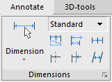
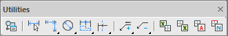
In nanoCAD, the dimensioning commands are available on the Annotate tab of the ribbon, the Dimensions main menu and the Utilities toolbar:
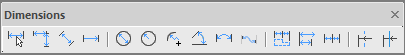
If necessary, you can use the Dimensions toolbar:
Some Features of nanoCAD’s Dimensioning
You can specify the size of dimensions in your drawing. Set the scale value using the Scale icon in the status line. Dimension scale affects the size of the dimension geometry relative to the objects in the drawing. At dimensioning, all size elements (height of the dimension text, size of the arrows etc.) are automatically scaled corresponding to the current dimension scale.
The Dimension scale is useful to dimension fragments drawn in the model space at the 1:1 scale. Their scale will change at arrangement on the worksheet.
For example, two views are drawn in the model space at the 1:1 scale. The first view will be placed on the layout at 1:1, the second view (based on its actual size) at 1:10. For dimensioning in the model space, you must specify the dimension scale as 1:1 for the first view and 1:10 for the second view. All elements of dimensioning of the first view will have values determined by the dimension style (for example, the height of the dimension text – 2.5 mm, the length of the arrows – 2.5 mm, etc.). The value of the second view dimensions will be automatically increased by 10 times (the height of the dimension text in the model space will be 25 mm, the length of the arrow – 25 mm), so that the dimensions are displayed correctly (the height of the dimension text – 2.5 mm, the length of the arrows – 2.5 mm, etc.) when this view is inserted on the layout.
When you change the dimension scale, the dimensions are not recalculated automatically.
To change any size of dimension scale, it is necessary to select it and select the required scale in the Measurement scale menu.
To set drawn dimensions to the current dimension scale, it is necessary to select the Set to selection command in Measurement scale menu and select the required dimensions on the drawing.
For more information on using scale, see «Symbol scale and measurement scale» section.