

-
-
-
-
-
-
-
-
-
-
-
-
-
-
-
-
-
-
-
-
-
-
-
-
-
-
-
-
-
-
Modify a Dimension Style
-
-
-
-
-
-
-
-
-
-
-
-
-
-
-
-
-
-
-
-
-
-
-
-
-
-
Modify a Dimension Style
The properties of new dimensions are set and options for existing dimension styles are modified in the Modify dimension style dialog box.
The name of the dimension style being modified is displayed in the dialog box title:
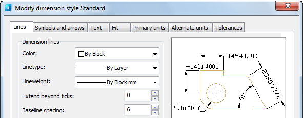
The Modify dimension style dialog box contains the following tabs:
· Lines
· Symbols and arrows
· Text
· Fit
· Primary units
· Alternate units
· Tolerance
The window in the upper right corner of each tab displays a graphical preview of the properties of the dimension style being modified.
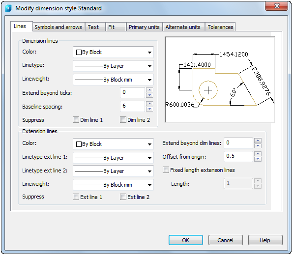
Sets the properties of dimension lines and extension lines:
Options:
Dimension lines
|
Color: |
Displays and sets the color for the dimension line. |
|
LineType: |
Sets the linetype of the dimension line. |
|
Lineweight: |
Sets the lineweight of the dimension line. |
|
Extend beyond ticks: |
Specifies the distance to extend the dimension line past the extension line when you use ticks and no marks for arrowheads. Examples: 1. Extend beyond ticks: 2
2. Extend beyond ticks: 0
|
|
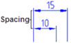
Baseline spacing: |
Sets the spacing between the dimension lines of a baseline dimension.
|
|
Suppress: Dim line 1, Dim line 2 |
Suppresses the display of dimension lines. Examples: 1. Dim Line 1 suppresses the first dimension
2. Dim Line 2 suppresses the second dimension line
|


Extension lines
|
Color: |
Sets the color for the extension lines. |
|
Linetype ext line 1: |
Sets the linetype of the first extension line. |
|
Linetype ext line 2: |
Sets the linetype of the second extension line. |
|
Lineweight: |
Sets the lineweight of the extension line. |
|
Suppress: Ext line 1, Ext line 2 |
Suppresses the display of extension lines. Examples: 1. Ext Line 1 suppresses the first extension line
2. Ext Line 2 suppresses the second extension line
|
|
Extend beyond dim lines: |
Specifies the distance to extend the extension lines above the dimension line. Examples: 1. Extend beyond dimension line: 1.25
2. Extend beyond dimension line: 0
|
|
Offset from origin: |
Sets the distance to offset the extension lines from the points on the drawing (object) that define the dimension. Examples: 1. Offset from object: 0.625
2. Offset from object: 0
|
|
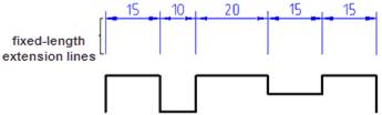
Fixed Length Extension Lines |
Enables fixed length extension lines. |
|
Length: |
Sets the total length of the extension lines.
|


Sets the format and placement for arrowheads, center marks, arc length symbols and jogged radius dimensions:
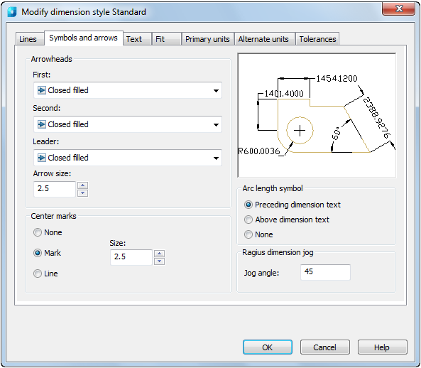
Options:
Arrowheads
|
First: |
Sets the arrowhead for the first dimension line. When you change the first arrowhead type, the second arrowhead automatically changes to match it. |
|
Second: |
Sets the arrowhead for the second dimension line. When you change the second arrowhead type, the first arrowhead does not automatically change to match it. |
|
Leader: |
Sets the arrowhead for the leader line. |
|
Arrow size: |
Displays and sets the size of arrowheads. |
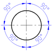
Center marks
|
None: |
Creates no center mark or centreline. |
|
Mark: |
Creates a center mark. |
|
Line: |
Creates a centerline. |
|
Size: |
Displays and sets the size of the center mark or centreline. |
Arc length symbol
|
Preceding Dimension Text: |
Places arc length symbols before the dimension text. |
|
Above Dimension Text: |
Places arc length symbols above the dimension text. |
|
None: |
Suppresses the display of arc length symbols. |
Radius dimension jog
|
Jog angle: |
Determines the angle of the transverse segment of the dimension line in a jogged radius dimension. |
Sets the format, placement, and alignment of dimension text:
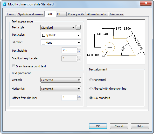
Options:
Text appearance
|
Text style: |
Lists the available text styles. |
|
|
Displays the Text styles dialog box where you can create or modify text styles. |
|
Text color: |
Sets the color for the dimension text. |
|
Fill color: |
Sets the color for the text background in dimensions. |
|
Text height: |
Sets the height of the current dimension text style. If a fixed text height is set in the Text Style (that is, the text style height is greater than 0), that height overrides the text height set here. |
|
Fraction height scale: |
Sets the scale of fractions relative to the dimension text. This option is available only when Fractional is selected as the Unit Format on the Primary Units tab. The value entered here is multiplied by the text height to determine the height of dimension fractions relative to dimension text. |
|
Draw frame around text |
When selected, draws a frame around the dimension text. |

Text placement
|
Vertical: |
Controls the vertical placement of the dimension text in relation to the dimension line: · Centered – Centres the dimension text between the two parts of the dimension line.
· Above - Places the dimension text above the dimension line. The distance from the dimension line to the baseline of the lowest line of text is the current text gap.
· Outside - Places the dimension text on the side of the dimension line farthest away from the first defining point.
· JIS - Places the dimension text to conform to a Japanese Industrial Standards (JIS) representation.
|
|
Horizontal: |
Controls the horizontal placement of the dimension text along the dimension line in relation to the extension lines: · Centered – Centers the dimension text along the dimension line between the extension lines.
· At Ext Line 1 - Left justifies the text with the first extension line along the dimension line. The distance between the extension line and the text is twice the arrowhead size plus the text gap value.
· At Ext Line 2 - Right justifies the text with the second extension line along the dimension line. The distance between the extension line and the text is twice the arrowhead size plus the text gap value.
· Over Ext Line 1 - Positions the text over or along the first extension line.
· Over Ext Line 2 - Positions the text over or along the second extension line.
|
|
Offset from dim line: |
Sets the current text gap, which is the distance around the dimension text when the dimension line is broken to accommodate the dimension text. This value is also used as the minimum length required for dimension line segments. Text is positioned inside the extension lines only if the resulting segments are at least as long as the text gap. Text above or below the dimension line is placed inside only if the arrowheads, dimension text and a margin leave enough room for the text gap. Examples: 1. Offset from dim line: 0.625
2. Offset from dim line: 0
|


Text alignment
|
Horizontal: |
Places text in a horizontal position.
|
|
Aligned with dimension line: |
Aligns text with the dimension line. |
|
ISO standard: |
Aligns text with the dimension line when text is inside the extension lines, but aligns it horizontally when text is outside the extension lines.
|


Controls the placement of the dimension text, arrowheads, leader lines and the dimension line:
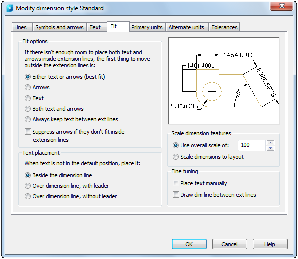
Options:
|
Fit options |
Controls the placement of text and arrowheads based on the space available between the extension lines. |
|
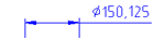
Either text or arrows (best fit): |
Moves either the text or the arrowheads outside the extension lines based on the best fit. |
|
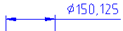
Arrows: |
Moves the arrowheads outside the extension lines first, then the text. |
|
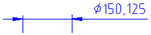
Text: |
Moves the text outside the extension lines first, then the arrowheads.
|
|
Both text and arrows: |
When not enough space is available for text and arrowheads, both are moved outside the extension lines.
|
|
Always keep text between ext lines: |
Always places the text between the extension lines. |
|
Suppress arrows if they don’t fit inside extension lines: |
Suppresses arrowheads if not enough space is available inside the extension lines. |
|
Text placement |
Sets the placement of the dimension text when it is moved from the default position; that is, the position defined by the dimension style. |
|
Beside the dimension line: |
If selected, moves the dimension line whenever the dimension text is moved.
|
|
Over dimension line, with leader: |
If selected, dimension lines are not moved when text is moved. If text is moved away from the dimension line, a leader line is created connecting the text to the dimension line. The leader line is omitted when text is too close to the dimension line.
|
|
Over dimension line, without leader: |
If selected, dimension lines are not moved when text is moved.
|


Scale dimension features
|
Use overall scale of: |
Sets a scale for all dimension style settings that specify size, distance or spacing, including text and arrowhead sizes. |
|
Scale dimensions to layout: |
Determines a scale factor based on the scaling between the current model space viewport and the paper space. |
Fine tuning
|
Place text manually: |
Places the text at the position you specify at the Dimension Line Location prompt. Ignores any horizontal justification settings. |
|
Draw dim line between ext lines: |
Draws dimension lines between the measured points, even when the arrowheads are placed outside the measured points. |
Sets the format and precision of the primary dimension units and sets prefixes and suffixes for the dimension text:
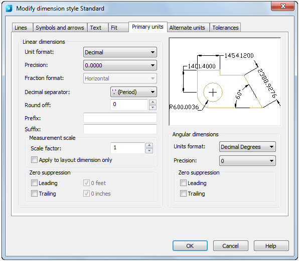
Options:
Linear dimensions
|
Unit format: |
Sets the current units format for all dimension types except Angular. |
|
Precision: |
Displays and sets the number of decimal places in the dimension text. |
|
Fraction format: |
Sets the format for fractions. Options are available if you have set the Fractional or Architectural values in the Unit format option. |
|
Decimal separator: |
Sets the separator for decimal formats. Options are available if you have set the Decimal value in the Unit format option. |
|
Round off: |
Sets rounding rules for dimension measurements for all dimension types except Angular. For example: 1. If you enter a value of 0.25, all distances are rounded to the nearest 0.25 unit. 2. If you enter a value of 1.0, all dimension distances are rounded to the nearest integer. The number of digits displayed after the decimal point depends on the Precision setting. |
|
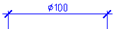
Prefix: |
Includes a prefix in the dimension text. You can enter text or use control codes to display special symbols. For example: Entering the control code %%c displays the diameter symbol. When you enter a prefix, it overrides any default prefixes such as those used in diameter and radius dimensioning.
|
|
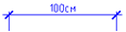
Suffix: |
Includes a suffix in the dimension text. You can enter text or use control codes to display special symbols. When you enter a suffix, it overrides any default suffixes.
|
Measurement scale
|
Scale factor: |
Defines the linear scale options. Scale factor set by default – 1. For example: If you enter 2, the dimension for a 100 millimetre line is displayed as 200 millimetres. The value does not apply to angular dimensions and is not applied to rounding values or to plus or minus tolerance values. |
|
Apply to layout dimension only: |
Applies the measurement scale factor only to dimensions created in layout viewports. Except when using non-associative dimensions, this setting should remain unchecked. |
Zero suppression
|
Leading: |
Suppresses leading zeros in all decimal dimensions. For example: 0.3000 becomes .3000. |
|
Trailing: |
Suppresses trailing zeros in all decimal dimensions. For example: 30.0000 becomes 30. |
|
0 feet: |
Suppresses the feet portion of a feet-and-inches dimension when the distance is less than one foot. For example: 0'-6 1/2" becomes 6 1/2". Options are available if you have set the Engineering or Architectural values in the Unit format option. |
|
0 inches: |
Suppresses the inches portion of a feet-and-inches dimension when the distance is an integral number of feet. For example: 1'-0" becomes 1'. Options are available if you have set the Engineering or Architectural values in the Unit format option. |
Angular dimensions
|
Unit format: |
Sets the angular units format. |
|
Precision: |
Sets the number of decimal places for angular dimensions. |
Zero suppression
|
Leading: |
Suppresses leading zeros in angular decimal dimensions. For example: 0.3000 becomes .3000. |
|
Trailing: |
Suppresses trailing zeros in angular decimal dimensions. For example: 30.0000 becomes 30. |
Specifies the display of alternative units in dimension measurements and sets their format and precision:
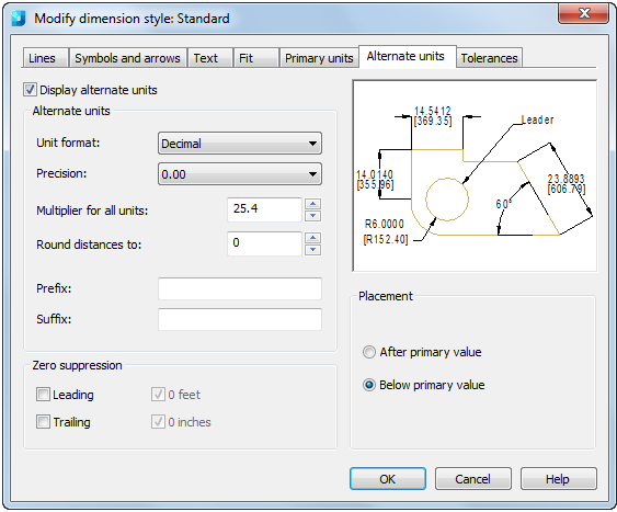
Options:
|
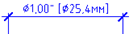
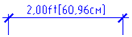
Display alternate units: |
Adds alternative measurement units to the dimension text. |
Alternate units
|
Unit format: |
Sets the unit format for alternative units. |
|
Precision: |
Sets the number of decimal places for alternative units. |
|
Multiplier for all units: |
Specifies the multiplier used as the conversion factor between primary and alternative units. For example: To convert inches to millimetres, enter 25.4. The value has no effect on angular dimensions and it is not applied to the rounding value or the plus or minus tolerance values. |
|
Round distance to: |
Sets rounding rules for alternative units for all dimension types except Angular. For example: 1. If you enter a value of 0.25, all alternate measurements are rounded to the nearest 0.25 unit. 2. If you enter a value of 1.0, all dimension measurements are rounded to the nearest integer. The number of digits displayed after the decimal point depends on the Precision setting. |
|
Prefix: |
Includes a prefix in the alternative dimension text. You can enter text or use control codes to display special symbols. For example: Entering the control code %%c displays the diameter symbol. When you enter a prefix, it overrides any default prefixes such as those used in diameter and radius dimensioning.
|
|
Suffix: |
Includes a suffix in the alternative dimension text. You can enter text or use control codes to display special symbols. When you enter a suffix, it overrides any default suffixes.
|
Zero suppression
|
Leading: |
Suppresses leading zeros in all decimal dimensions. For example: 0.3000 becomes .3000. |
|
Trailing: |
Suppresses trailing zeros in all decimal dimensions. For example: 30.0000 becomes 30. |
|
0 feet: |
Suppresses the feet portion of a feet-and-inches dimension when the distance is less than 1 foot. For example: 0'-6 1/2" becomes 6 1/2". Options are available if you have set the Engineering or Architectural values in the Unit format option. |
|
0 inches: |
Suppresses the inches portion of a feet and inches dimension when the distance is an integral number of feet. For example: 1'-0" becomes 1'. Options are available if you have set the Engineering or Architectural values in the Unit format option. |
Placement
|
After primary value: |
Places the alternative units after the primary units in the dimension text. |
|
Below primary value: |
Places the alternative units below the primary units in the dimension text. |
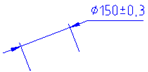
Controls the display and format of the dimension text tolerances:
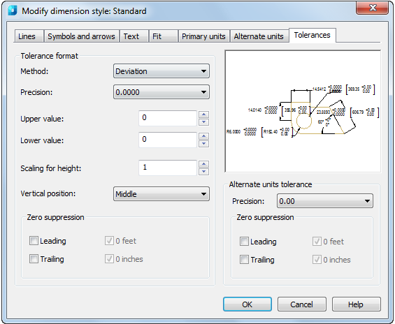
Option:
Tolerance format
|
Method: |
Sets the method for calculating the tolerance: · None - Does not add a tolerance.
· Symmetrical – Adds a plus/minus expression of tolerance in which a single value of variation is applied to the dimension measurement. A plus-or-minus sign appears after the dimension. Enter the tolerance value in Upper Value.
· Deviation – Adds a plus/minus tolerance expression. A plus sign (+) precedes the tolerance value entered in Upper Value, and a minus sign (-) precedes the tolerance value entered in Lower Value.
Note: If you input a minus sign (-) before an upper maximum deviation value, the value will be displayed with a minus sign (-) on the drawing.
Note: If you input a minus sign (-) before a lower maximum deviation value, the value will be displayed with a plus sign (+) on the drawing. · Limits – Creates a limit dimension. A maximum and a minimum value are displayed, one over the other. The maximum value is the dimension value plus the value entered in Upper Value. The minimum value is the dimension value minus the value entered in Lower Value.
· Basic – Creates a basic dimension, which displays a box around the full extent of the dimension.
|
|
Precision: |
Sets the number of decimal places. |
|
Upper value: |
Sets the maximum or upper tolerance value. When you select Symmetrical in Method, this value is used for the tolerance. |
|
Lower value: |
Sets the minimum or lower tolerance value. |
|
Scaling for height: |
Sets the current height for the tolerance text. The ratio of the tolerance height to the main dimension text height is calculated. |
|
Vertical position: |
Controls the text justification for symmetrical and deviation tolerances: · Bottom - Aligns the tolerance text with the bottom of the main dimension text.
· Middle - Aligns the tolerance text with the middle of the main dimension text.
· Top - Aligns the tolerance text with the top of the main dimension text.
|


Zero suppression
|
Leading: |
Suppresses leading zeros in all decimal dimensions. For example: 0.3000 becomes .3000. |
|
Trailing: |
Suppresses trailing zeros in all decimal dimensions. For example: 30.0000 becomes 30. |
|
0 feet: |
Suppresses the feet portion of a feet and inches dimension when the distance is less than 1 foot. For example: 0'-6 1/2" becomes 6 1/2". Options are available if you have set the Engineering or Architectural values in the Unit format option. |
|
0 inches: |
Suppresses the inches portion of a feet-and-inches dimension when the distance is an integral number of feet. For example: 1'-0" becomes 1'. Options are available if you have set the Engineering or Architectural values in the Unit format option. |
Alternate units tolerance
|
Precision: |
Displays and sets the number of decimal places. |
Zero suppression
|
Leading: |
Suppresses leading zeros in all decimal dimensions. For example: 0.3000 becomes .3000. |
|
Trailing: |
Suppresses trailing zeros in all decimal dimensions. For example: 30.0000 becomes 30. |
|
0 feet: |
Suppresses the feet portion of a feet-and-inches dimension when the distance is less than 1 foot. For example: 0'-6 1/2" becomes 6 1/2". Options are available if you have set the Engineering or Architectural values in the Unit format option. |
|
0 inches: |
Suppresses the inches portion of a feet-and-inches dimension when the distance is an integral number of feet. For example: 1'-0" becomes 1'. Options are available if you have set the Engineering or Architectural values in the Unit format option. |