

-
-
-
-
-
-
-
-
-
-
-
-
-
-
-
-
-
-
-
-
-
-
-
-
-
-
-
-
-
-
-
-
Comb Leader Note
-
-
-
-
-
-
-
-
-
-
-
-
-
-
-
-
-
-
-
-
-
-
-
Comb Leader Note
 Ribbon: Home, Annotate – Leaders >
  Comb Leader note
Menu: Draw – Notes >  Comb leader notes…
 Toolbar: Utilities –
 Command line: NOTEC
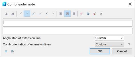
This command opens the Comb leader note dialog box to set the comb leader note options:
Options:
Buttons to add borders:
|
|
Managing multiline text output above the leader. |
|
|
Framing the text under the leader. |


Use the icons to select the style of the extension line:
|
|
None. |
|
|
Arrow. |
|
|
Point. |
|
|
Open arrow. |
|
|
Half-arrow. |
|
|
Oblique. |


Use the icons to select the text alignment method:
|
|
By left edge. |
|
|
By center. |
|
|
By right edge. |


Other icons and options:
|
|
The Insert special symbol icon opens the panel with the table of special symbols, to select and insert them at the current cursor position in the text input field. |
|
|
The Notepad icon opens the Notepad dialog box. |
|
|
The Match properties icon temporarily closes the dialog box to specify the inserted leader whose properties should be copied and applied to the newly-created leader. |
|
|
The Add extension line icon is used to insert additional extension lines. The icon is enabled when you edit a leader inserted into the drawing. |
|
|
The Select line icon is used to switch the comb orientation parallel to the specified line on the drawing. The icon is available when you edit the comb leader note inserted into the drawing. |
|
Angle step of extension lines: |
Drop-down list to select inclination. In the list the following inclinations are available: · Custom - the extension line is placed arbitrarily (by default); · 15 - the extension line is placed in step multiples of 15°; · 30 - the extension line is placed in step multiples of 30°; · 45 - the extension line is placed in step multiples of 45°; · 90 - the extension line is placed in step multiples of 90°. |
|
Comb orientation of extension lines: |
Drop-down list to select the comb orientation of the extension line. The following options are available in the list: · Custom · Horizontal · Vertical |
|
|
The Options button opens the nanoCAD Design Settings dialog box – Symbols tab. |


Right-click in the text field and choose the required menu item:
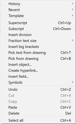
For more information about additional commands, see the Mechanical Note section.
To create a comb leader note:
1. Type the required text into the text fields.
2. Select the required leader options.
3. Click OK.
4. Specify the leader’s position and press ENTER to end.
5. Specify the leader’s position and angle. In the command line the following prompts are displayed: [Horizontal /Vertical /Parallel]. The Parallel option allows you to choose the direction of a comb leader note parallel to any line on the drawing.
6. Specify the shelf position on the drawing.