

-
-
-
-
-
-
-
-
-
-
-
-
-
-
Bounding Prism
-
-
-
-
-
-
-
-
-
-
-
-
-
-
-
-
-
-
-
-
-
-
-
-
-
-
-
-
-
-
-
-
-
-
Bounding Prism
 Ribbon: View – Visibility Manager >
  Bounding Prism
Menu: View >  Bounding Prism
Menu: Modify – Clip > Bounding Prism
Toolbar: View toolbar > Bounding Prism
 Command line: MCLIP
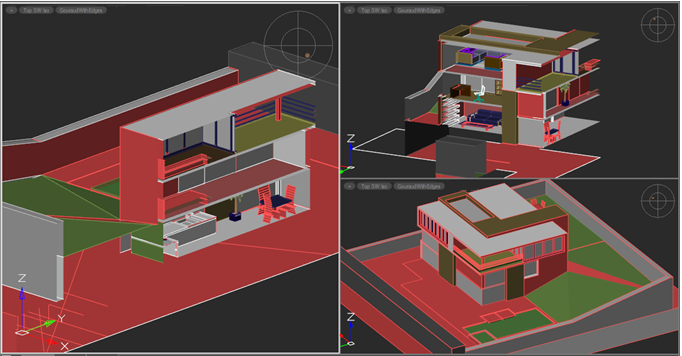
For each model or paper space viewport, you can create a bounding prism – an area in a three-dimensional space, beyond which all the graphics are not displayed.
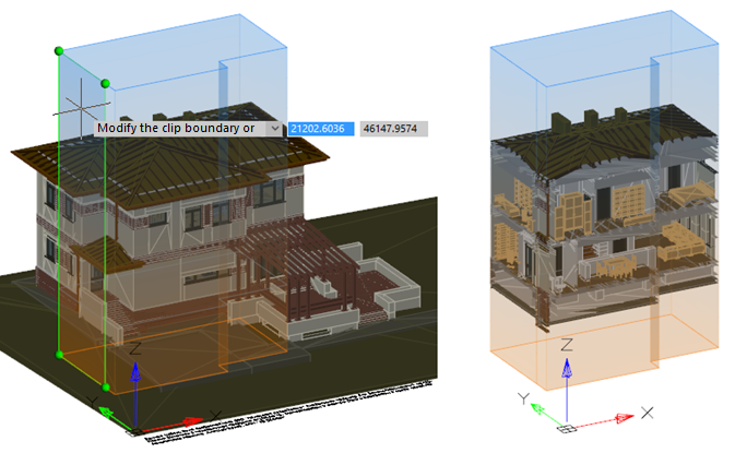
The area is defined as a rectangular or polygonal object. The prism can be created by specifying a contour on the screen, on the basis of an existing polyline, based on a bounding box of selected objects. The prism can be stretched, compressed, and resized by dragging any edges and faces in any place.
So, you can grab any area of the visible face and move it along its normal (in the case of a rectangular prism) or in any direction (in the case of a polygonal prism). Snaps and orthographic drawing modes can be used. Hidden faces can be moved by grabbing one of their edges. The entire prism can be dragged while holding down CTRL.
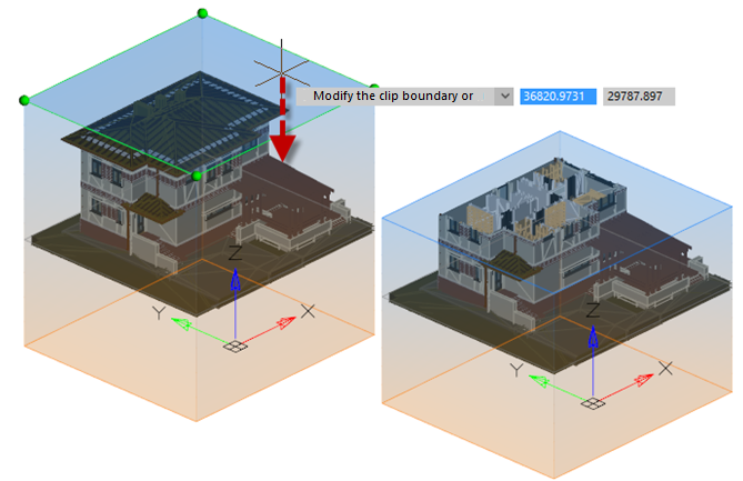
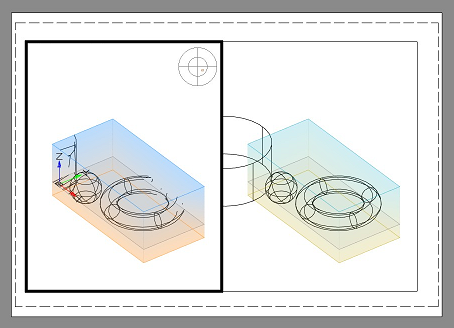
The prism is built taking into account the direction of the UCS axes. The prism above the XY plane of the UCS is blue, below it is orange. The grey outline of the prism is displayed in the XY plane.
A bounding prism is created for each viewport. It will not restrict the image in other viewports.
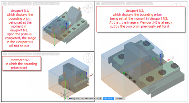
At the time of creating or editing a prism, it is displayed in all viewports, but its effect only applies to the screen in which it was created or was selected for editing. When you finish adjusting the prism, it will crop the image only in the viewport for which it was created.
To create a new or edit an existing prism, go to the desired viewport and run the Bounding prism command.
While editing a prism, you can switch to another viewport to continue editing it from a more comfortable angle. At the same time, editing of the prism that belongs to the previous viewport (in which the Bounding Prism Bounding prism command was run) will continue in the new viewport, and not the current one. A prism in its own viewport is displayed more vividly than in the others so that it is always clear which viewport it belongs to, regardless of which viewport is currently active.
When saving a document, prisms are also saved for their viewports.
An existing prism can be changed, deleted or disabled/enabled. If the prism is disabled, graphics outside the prism become visible. Disabled prism object is still present in the model space and can be switched on later.
Options:
|
New |
Creates a new bounding prism for the current view of the model space. |
|
Delete |
Deletes the existing bounding prism in the current view of the model space. |
|
|
|
|
Enable |
Activates the effect of an existing prism on the current view of the model space. Enabled by default. |
|
Disable |
Inactivates the effect of an existing prism on the current view of the model space. Prism is preserved, but does not limit the space of the view. |
|
Exit |
Exits command. |
Options for creating a new prism:
Options appear when there is no prism in the viewport or when New option is selected.
|
polyLine |
Selects an existing closed polyline that will define the contour of the prism. Then, using grips, set the upper and lower prism cutoff boundary, if necessary. The prism will be built in the direction of the UCS axes of the current view. |
|
Selection |
Selects the objects around which a rectangular prism will be built. Then, using grips, change the upper and lower prism cutoff boundary, if necessary. |
|
Rectangular |
Draws a rectangular contour that will define the contour of the prism. Then, using grips, set the upper and lower prism cutoff boundary, if necessary. |
|
Polygonal |
Draws a polygonal contour that will define the contour of the prism. Then, using grips, set the upper and lower prism cutoff boundary, if necessary. |
|
eXit |
Finishes the process of creating a new prism. |