

-
-
-
-
-
-
-
-
-
-
-
-
-
-
-
-
-
-
-
-
-
-
-
-
-
-
-
-
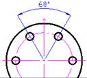
Angular Dimensions
-
-
-
-
-
-
-
-
-
-
-
-
-
-
-
-
-
-
-
-
-
-
-
-
-
-
-
Angular Dimensions
 Ribbon: Home, Annotate - Dimensions >
  Angular
Menu: Dimensions –  Angle dimension
Toolbar: Utilities –
 Command line: MDIMANG
To draw the angle between two segments:
1. Start the Auto command.
2. Place the cursor over one of the segments to show its dynamic highlighting and display the character  . Left click to confirm the dimensioning:

3. Place the cursor over the second segment to show its dynamic highlighting and display the character  . Left click to confirm the dimensioning:

4. Choose the location of the dimension:

5. Left click to set the location of the dimension line:

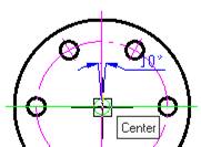
For dimensioning the angular dimension using characteristic points:
1. Start the Auto command.
2. Select the anGular option in the command line or context menu.
3. Specify the first point of the angular dimension (vertex of angle):
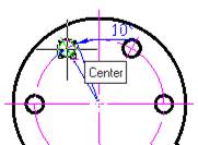
4. Specify the second point of the angular dimension:
5. Specify the third point of the angular dimension:
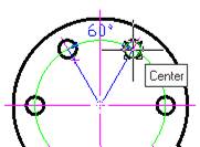
6. Specify the location of the dimension line:
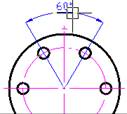
7. Press ENTER to finish the command
Ribbon: Home, Annotate - Dimensions >  Angle ordinate
Menu: Dimensions –  Angle ordinate dimension
Command line: dimaord