

-
-
-
-
-
-
-
-
-
-
Aligning UCS to an Object
-
-
-
-
-
-
-
-
-
-
-
-
-
-
-
-
-
-
-
-
-
-
-
-
-
-
-
-
-
-
-
-
-
-
-
Aligning UCS to an Object
 Ribbon: View – Coordinates >
  Object
Menu: Tools – Coordinate system > Object
 Toolbar: UCS –
 Command line: SETUCSBYOBJECT
The command specifies the new position of the coordinate system origin for the current UCS; the direction of the axes is specified according to the geometry of the current object. The extrusion direction of the selected object specifies the positive direction of the Z axis for the new UCS.
Rules to create UCS, aligned to an object:
|
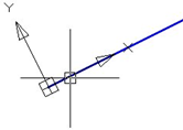
Line |
|
The origin of the new UCS is set at the line end which is closest to the selection point. The X axis is used to place the line in the XZ plane. The Y coordinate of the second end of the line is zero in the new UCS. |
|
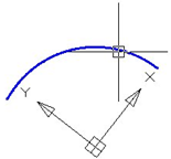
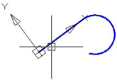
Arc |
|
The origin of the new UCS is the center of the arc. The X axis is set at the end of the arc which is closest to the selection point. |
|
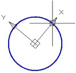
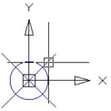
Circle |
|
The origin of the new UCS is the center of the circle. The X axis is set at the selection point. |
|
Point |
|
The origin of the new UCS is the selection point. |
|
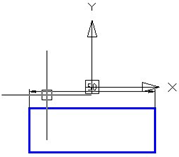
Polyline
|
|
The origin of the new UCS is the start point of the polyline. The X axis is set at the start point and the nearest polyline vertex. |
|
Dimension |
|
The origin of the new UCS is in the middle of the dimension text. The new X axis is set parallel to the X axis of the UCS used to specify the dimension. |
|
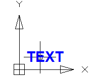
Text block insertion, attribute definition
|
|
The origin of the new UCS is the insertion point of the object and the direction of the X axis is set by the angle of object rotation around the direction of extrusion. The object used to set the new UCS has a zero-rotation angle in this UCS. |
Command prompt:
|
Select object to align UCS: |
Select an object. |