

Creating Parametric Objects in nanoCAD Mechanica Part 2
Working with the script of an object. Script Wizard
The first part of this article described the process of creating a library object and connecting geometry to it. The object we created has a basic script with basic functions, so it does not contain any variables so far. We need to modify the script in accordance with the functionality required of the object. Let's take the script of a similar library object to use as an example in this tutorial.
As mentioned in the first part, this article can be used as instructions to create and manage parametric objects.
Download an object we prepared for this tutorial by clicking on the Download the File for this article link at the beginning of the article.
First, isert the object to the library: right-click on the Sample folder in the Library to open the context menu and select Import Object (Figure 1). When a file explorer opens, browse the file downloaded. Select the file and click Open. The new object will be inserted.
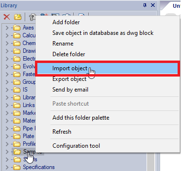
Figure 1
In the Script menu of the MechWizard, select Get script from other object. In the Select object window that appears, open the Samples folder, and click on the Washer object (Figure 2).
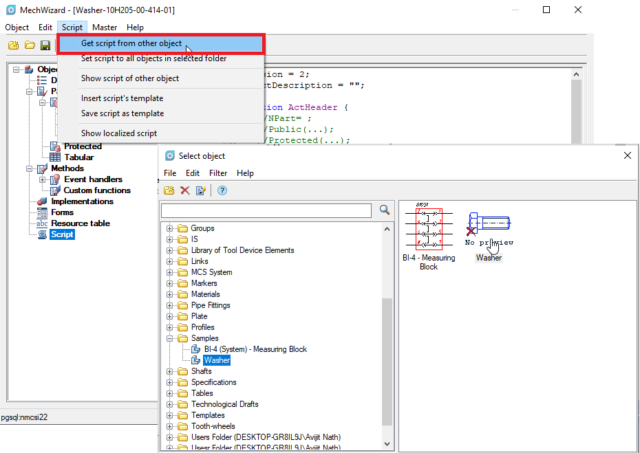
Figure 2
The script for the new object will get updated (Figure 3).
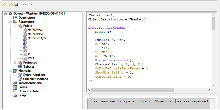
Figure 3
The object we copied the script from has a simpler geometry. Let's adapt this script to our object. To add parameters and set new values, select Script wizard in the Master menu and click Yes in the pop-up window that appears (Figure 4).
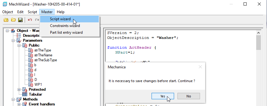
Figure 4
In General properties, add and/or edit information as shown in Figure 5. Click Next.
In the Object Name field, enter the name of the object as you want it to be displayed in the library.
The value in the Cover order (ZOrder) field controls the overlap of objects relative to each other in the assembly drawing.
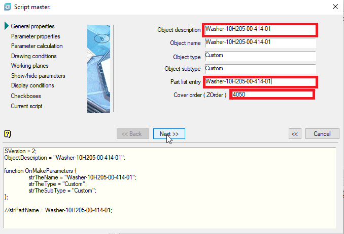
Figure 5
In the Parameter Properties window, add missing parameters and set their values. Let’s modify the existing parameter values in our example as follows:
b = 4; B = 6; D = 71.5; D1 = 0.75*D; d = 30; f = 1; l = 0
Then, let’s make all parameters available for editing: select a parameter and click Changeable (available for editing) (Figure 6).
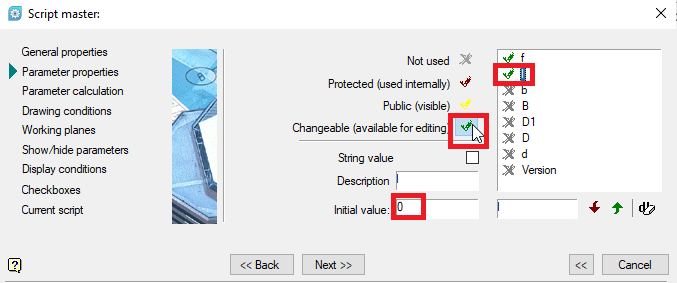
Figure 6
To add a parameter, enter a new name in the name field of an existing parameter and click the Add parameter button. Then, enter the Initial value to be assigned by default in the created parameter (Figure 7)
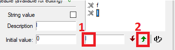
Figure 7
Next, let’s check the sequence of parameters. For the script to operate correctly, the D parameter must be higher than D1, since the latter is set by the formula through the former. You can always change the order of parameters with the arrow buttons if needed (Figure 8).
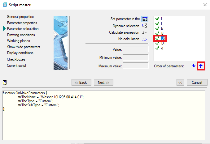
Figure 8
Then, without changing anything, click Next (Figure 9).
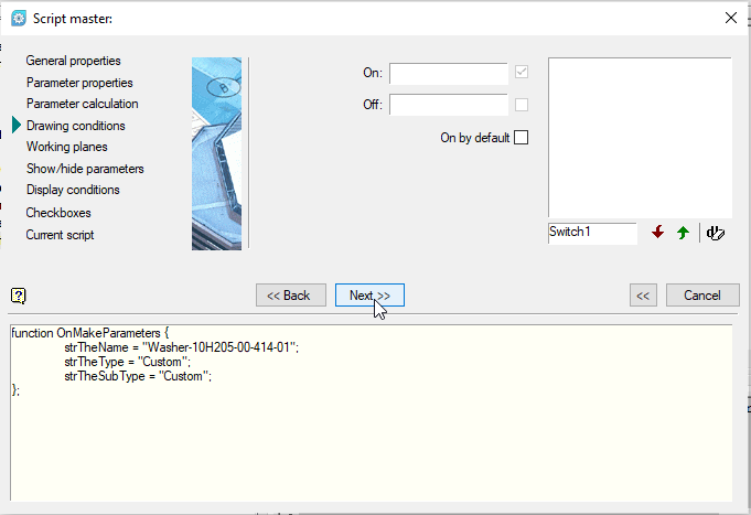
Figure 9
Now, let’s add a description of the working planes. It is necessary to impose dependencies between other components. Click the Add Plane button, set the OYZ orientation, and enable the Changeable (available for editing) option (Figure 10). Click Next.
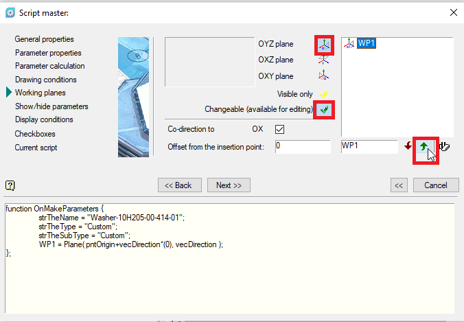
Figure 10
Let’s move forward to the next two steps without making any changes (Figure 11).
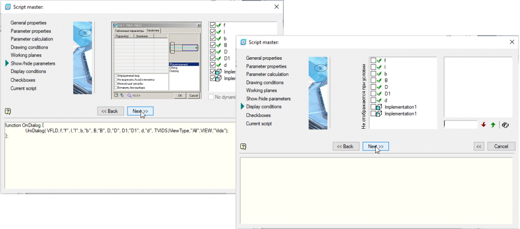
Figure 11
In the Checkboxes window, enable Show object while inserting (Figure 12).
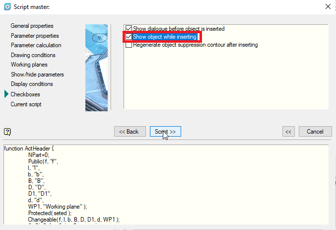
Figure 12
Finally, you can see the generated program script in the Script master. You can return back to any of the previous steps to make any changes needed.
Click OK and save the script (Figure 13).
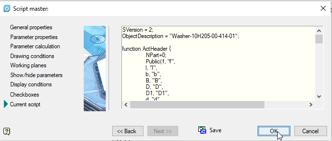
Figure 13
Now, let’s check how the new object operates. Save the changes made to the object and close the MechWizard.
In the library of standard parts, find the created object (the Users folder). If it is not displayed, click Refresh
Change the values of B to 4, and b to 2, and click OK. The washer geometry will be updated accordingly (Figure 14).
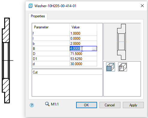
Figure 14
Now, you can double-click on the object to return to the parameter editing mode, and change the parameters again if needed. This might be useful, when such changes are made rarely. Given that the washer is one of the products constantly used in machine-building design, and you can usually have more than a dozen models, this option is not well-suited. It is better to create additional models with new values, which will save you time, as you will not have to go through unnecessary steps in the future.
This as well as how to create and manage assembly dependencies, will be discussed in the next part.