

New in
Version 24
You can open the toolbar in the ribbon interface in the Home and Settings tabs:


In the classic interface: menu View – Toolbars > Functional >
 Layer Manager… or in the Properties bar – Layer Manager…
The command for opening the Layers functional bar in the command line – LAYERSQUICK.
The list of layers can be presented in a tree or table view:


In the tree view, the names of layers are displayed in the left column, and the main properties in the form of icons are displayed in the right column (Status, Color, VP Color, Layer Visibility, Freeze, Lock, Plot, New VP Freeze, VP Freeze). The remaining parameters are expanded in a list under the layer name when you left-click on the arrow to the left of the layer name. The default display mode is a tree view.
In the table view, layer properties are displayed in the form of a table with columns; the functionality corresponds to the Layers dialog.
Due to addition of the Layer Manager functional bar, the old Layers dialog has now become modal, i.e., while the dialog displays all relevant information on the layers in it and changes outside configure dialog are not taken into account. The bar synchronizes and displays current data after closing the dialog.

The following properties have been added:
- material category;
- material;
- control group;
- additional parameters.
All these parameters can be selected in accordance with the requirements of the relevant standards. It has become more convenient to create a sign for flanges and flange blanks for specifications.
The bug due to which, when building in primitive 3D solids, the directions of X and Y axes of the current UCS were not taken into account, has been fixed.
 Standards settings,
  Configure,
  Check,
  Layer Translator.


And in nanoCAD Mechanics 24 a metric radius 3D thread has been added.
Now you can make 3D parts with such threads, both internal and external, in addition, such threads have appeared on base elements.

The bug due to which the graphics of 3D constraints were not highlighted on standard objects has been fixed
The bud has been fixed, where 3D Loft would highlight sketches that were not related to that Loft.
The bug has been fixed where auto constraints did not work when entering a sketch using CTRL+Z or CTRL+Y.
Now, when using the 3D Sweep command, the path being used is hidden by default.
The bug has been fixed where the extrusion did not occur on the contours of elements where infinite elements (RAY, XLINE) were used.
The bug that in some cases caused the program to freeze when using the extrude command has been fixed.
The description and tooltips of some 3D construction commands in the interface and on the 3D History bar have been corrected.
The bug in the 3D history that appeared when converting old versions of models has been fixed.
The program freezing when using the extrude command on some paths has been fixed.
The bug due to which, when canceling an action with CTRL+Z, auxiliary elements of constructions lost their connection with the object, has been fixed.
The bug due to which the selection of contours for extrusion was reset in some cases has been fixed.
The bug due to which extra parameters were displayed in the Parameter Manager when extruding by loft has been fixed.
The bug due to which in some complex cases elements were not added to the array has been fixed.
The command opens the Layer Translator dialog box:


Thus, now, when the setting is enabled, Construction design objects are oriented in accordance with the current coordinate system:
- Position marker;
- Level mark;
- Node designation;
- Fragment designation;
- Change marker;
- All types of leaders;
- Welded leg, welded seam, welded joints and cutting edges for welding;
- Permanent connection;
- Axes and array of axes;
- Slope designation;
- Picketage designation;
- Format;
- Table.
The format of angular units Deg/Min/Sec has been corrected.
The update of detail views from viewports has been corrected.
3D models of pipeline fittings for connections along the internal cone have been made.
3D models of plugs and stoppers have been made.

- Bend along line with angle inside.
- Bend along edge in the sketch plane.
- Bend with more than two lines.
Construction of sweeps on solids with NURBs-surface has been corrected.
- Coverings browser (COVERINGBROWSER)

- Covering editor (COVERINGEDITOR)

- Texture editor

- File Explorer (FILEEXPLORER, ADCENTER)


The possibility to redefine blocks has been added to the File Explorer functional bar. The Insert and Redefine and Redefine only commands are available in the block context menu
 .
.


It also became possible to add closed structural lines, including with deleting points inside the contour.


The bug in the Stamp Creation Wizard has been fixed. Due to it the thickness and color of the stamp lines could not be determined by the design settings.
The drawing of Tooth wheels has been corrected.
Sheet Solids
The bugs have been fixed, due to which a bend was not created according to a sketch:
- along line with angle inside
- along edge in the sketch plane
- with more than two lines
Construction of sweeps on solids with NURBs-surface has been corrected.

The Area (AREA) and Cumulative Area (CAREA) commands now calculate area, including for objects of the Region (REGION) type.


The behavior of the Plot dialog when there is no plotting device (printer/pc3) specified in the document has been fixed. The Internal PDF-plotter will now be used. In this case, whenever possible, the format dimensions and orientation specified in the pc3 file or document are preserved. The Internal PDF-plotter will select a format that exactly matches the size specified in the document or pc3, or the next larger one from the list of formats available for that plotter.

In the OPTIONS dialog box, in the Import/Export and Print Settings section, a new option has been added: Plot temporary hidden objects:

It controls the printing of objects that are temporarily hidden by the HIDEOBJECTS or ISOLATEOBJECTS commands. When the option is enabled, hidden objects in temporary isolation mode (system variable OBJECTISOLATIONMODE = 0) are printed; when disabled, they are not printed. By default, the option is disabled; temporarily hidden objects are not printed.
In the Page Setup dialog, the name of the Frame Width field has been changed to the Frame Weight. The field is available when the To file mode is enabled.


- CTRL+SHIFT+SPACEBAR – inserts a non-breaking space in texts;
- CTRL+B – enables/disables the bold style for new or selected text;
- CTRL+I – enables/disables italics for new or selected text;
- CTRL+U – enables/disables underlining for new or selected text;
- CTRL+O – enables/disables overlining for new or selected text.
It has become possible to automatically set the frame width to fit the text size by double-clicking the left mouse button on the
 element of the text input window.
It has now become possible to switch from the “text insertion” mode (text is entered starting from the insertion point) to the “text replacement” mode (text entered from the keyboard replaces previously typed text) using the INSERT key.


The colored rays are directed from the origin of coordinates. Red is assigned to the X-axis and green to the Y-axis. Display is enabled/disabled when the grid is enabled/disabled (command line: GRID; hotkeys: F7, Ctrl+G).

Default GRIDSTYLE = 0 – the grid is displayed as lines in model space, block editor, layouts, and paper space layouts. The following variable values are also available:
GRIDSTYLE = 1 – display of grid as dots in 2D model space.
GRIDSTYLE = 2 – display of grid as dots in the block editor.
GRIDSTYLE = 4 – display of grid as dots in layouts and paper space layouts.
You can also set up the Grid style in the Drafting settings (command line: DDRMODES, DSETTINGS, SE).


The function allows you to copy the following properties within one multiline text: font, height, style (bold, italic, strikethrough, underline, overline), skew, tracking (character spacing), aspect ratio, text color, text alignment (left, center, justify, right, distributed), line spacing, bulleted and numbered list options, paragraph options (indents, tab stops).
To use the function, you need to select a part of the text or place the cursor on the text whose formatting you want to copy. On the Text format bar, click the Copy Text Format button. Select the text to be formatted. To complete formatting, press ESC or uncheck the Copy text format button.
You can configure the settings in the Options dialog box (Command line: OPTIONS, PREF; hotkeys: Ctrl+9) in the Standard Audit Usage section.

Options in the Standard Audit Usage section:
- No – prohibition to attach the standard file to drawings being opened. The option is selected by de-fault;
- Use for all documents – use the standard file for all documents being opened;
- Standard Audit File Name <> – setting the *.dws standard file.
When a standard file is assigned in the STANDARDS command dialog box, the file will be displayed first in the list.


The generated package of files includes an information file with a *.txt extension, containing a list of all files (including folders), instructions and notes for users.
The command is supplemented with the following settings:
- setting the root folder to form an organized folder structure;
- inclusion of textures created and/or used in the drawing in the file package;
- inclusion of point cloud in the file package;
- inclusion of unloaded external references in the file package.


The functionality of the command to construct a circle using 2 tangency points and a radius has been improved
The set of model viewport configurations has been expanded:

The commands are available in the Ribbon: View – Model Viewports – Viewport Configuration and in the classic interface Menu: View – Viewports, Toolbar: Viewports.
Now, when copying properties of a polyline using the MATCHPROP command, in addition to the width, the linetype generation is also copied.
The standard Coverings library has been supplemented with new textures in the sections of Wood, Roofing, Landscape Design, as well as with a new Water section.

The possibility to delete the Defpoints layer (a service layer containing control points) using the LAYDEL command has been added. During further work with the document, when setting dimensions, the layer will be created again.
The possibilities for inserting blocks into mcad objects (tables, leaders) have been expanded. Now, using the Explode Geometry command, you can also add blocks with the Allow Explosion – No option.
The possibility to expand the expression input field in the Table edit dialog.

The possibility to install the PostGIS extension for PostgreSQL has been added to the program distributive. The extension is necessary to use the functionality of Databases when storing point clouds. If you do not plan to work with point clouds, you can skip this step during installation.

The Properties (INSPECTOR) functional bar for a block now displays the Uniform scale property that is set when the block definition is created. You can change it in the block editor (BEDIT).
- Formatting has been improved;
- Symbols for collapsing groups of elements (arrows) have been added.
It concerns the dialogs for import, export, conversion of geopoints, as well as splitting a point cloud into geopoints.


The bug due to which text was not displayed in table cells with vertical text direction when top center and top right alignment was selected in the preview window of the Edit table menu has been fixed.

The bug due to which the selection of objects in the report filter was reset if previously added objects did not match the filter conditions has been fixed.
The bug due to which it was impossible to insert a block into a table cell has been fixed.
The bug due to which the contents of the IFC tab were not loaded immediately when starting a new session has been fixed.
The crash when clicking the Select button (Navigation and selection) while the drawing name is selected in the Drawing Explorer (DRAWINGEXPLORER) has been fixed.
The crash that occurred after renaming a VP Configuration using invalid characters has been fixed.
The crash that occurred when closing a drawing without saving after inserting and clipping a map background (MAPVIEW, CLIPMAP) has been fixed.
The bug that caused the program to freeze and crash when the file size was more than 1 GB has been fixed.
The crash has been fixed and the platform’s performance with drawings containing external links to large ECW rasters has been optimized. Now work with the file is organized in parts (up to 64 MB). Printing of such drawings is possible from model space using, for example, the Internal PDF-plotter.

The error has been fixed, due to which external references (XATTACH) with long names were being selectively inserted when multiple files were selected at the same time. You can now select many files with long names. The maximum number of references to be loaded is limited to 200. A bug has also been fixed that caused drawings to be inserted at different scales when inserting external references at the same time.
The error with the FIELD command has been fixed, when in the Formula, when entering an expression with brackets, the outer brackets were removed, which led to calculation errors.
The operation of the Stop button in the Batch Processing dialog (BATCHPROCESS) has been corrected.
The situation has been fixed when warning messages about standard violations appeared in the Reference Edit (REFEDIT) mode.
The bug has been fixed due to which a duplicate ellipse would appear when scaling a circle or arc unevenly.
The bug has been fixed that resulted in size associativity being lost after the Change Space (CHSPACE).
The bug with the availability of text parameters (text height, rotation) with the “Width” and “Fit” alignment options in the Attribute Definition (ATTDEF) window has been fixed.
The operation of the NEWLAYER command has been corrected; the possibility to enter names of new layers with spaces has been added.
The line weight has been limited to 200 mm in the Create & Edit Plot Style Table (PLOTSTYLEMANAGER).
The bug due to which underlays in DWF format were not inserted into a drawing using the UATTACH command has been fixed.
The error that occurred when synchronizing the attributes of block references (ATTSYNC) in blocks with attributes that included a formula with an attribute field of the same block has been fixed.
The bug that resulted in the viewport lock button not working if the viewport was clipped by a polyline has been fixed.
The bug has been fixed due to which it was impossible to select a fill angle equal to 360 degrees when creating and editing a Polar Array (ARRAYPOLAR).
The number of errors due to which it was possible to edit multileader text on a locked layer have been fixed.
The error due to which block attributes were not displayed after inserting it into a new file has been fixed.
The bug has been fixed due to which the status of an external reference in the External References toolbar was not updated when it was updated.
The bug has been fixed due to which texts in annotative blocks with two scales were not printed.
The situation where adding an external reference (ATTACH) to a 2D block would convert it to a 3D block has been fixed.
The bug has been fixed due to which new field format options (FIELD) were not applied after editing.
The bug has been fixed due to which the export of the drawing area (СОХРВРАСТР) in WMF format was not performed.
The bug has been fixed due to which fields in multileaders (MLEADER) with the Right attachment – Underline top line style turned into text.
The bug has been fixed due to which the custom width of a multiline attribute was not scaled when scaling (SCALE) a block (BLOCK).
The situation where *.png format rasters were not loaded when importing *.dxf files has been fixed.
The bug due to which auto-recalculation did not work in a table with blocks whose names began with the “_” character (underscore) has been fixed.
The bug has been fixed due to which, when inserting a template sheet into a new file using the LAYOUTFROMTEMPLATE command, definitions of blocks located on other sheets or in model space were also added to the drawing.
The bug due to which information on the Region (REGION) object was displayed incorrectly in table cells has been fixed.
The mechanism for displaying a message about standards violations has been corrected. The message now closes automatically when you click on a link in it or when a standards check is started.
The bug has been fixed due to which blocks in table cells were displayed incorrectly after adding rows to the table.
The situation has been fixed when the Update view to Plan when UCS is changed (UCSFOLLOW system variable) did not change when switching between UCSs through the Properties functional bar.
The bug that caused sorting by date in the External References functional bar to work incorrectly has been fixed.
The bug due to which fields with document properties in tables were not edited or updated when dividing the table into pages has been fixed.
The bug due to which standards files (*.dws) were not displayed in the File Explorer has been fixed.
The bug has been fixed due to which after creating and applying a page setup (PAGESETUP) to another layout, zooming would not occur correctly and drawing limits would not be displayed.
The bug due to which external references were duplicated in the External References (EXTERNALREFERENCES) functional bar has been fixed.
The bug has been fixed that caused the raster selection border to become rasterized. Now, when performing rasterization operations, only that part of the selection that is located within the boundaries of the resulting image is rasterized.
The errors in the operation of the FIELDEVAL variable have been fixed. Now all variable values work as described.
The bug has been fixed due to which MTEXT with bold and/or italic formatting created in the current version of the program was displayed in older versions with formatting symbols.
The platform’s performance has been accelerated when editing dimensions using grips (GRIP).
The bug has been fixed due to which some objects (nanoCAD tables (TABLE), coordination axes (SPCLINE, SPGRID, SPPGRID, SPARCCLINE, SPCIRCCLINE), slope designation (SPGRAD)) were created rotated if the current UCS was rotated relative to the WCS. Now the tables are oriented relative to the WCS.
The behavior of the Frame weight (formerly Frame width) field in the Page Setup and Plot dialogs has been corrected. Now the parameter is available only when the Fit to paper mode.
The bug due to which when pasting a cropped block via the clipboard, the block was inserted uncropped has been fixed.
Problems with isometric grid drawing have been fixed (grid lines were located at double of the distance specified in the settings).
The Find and Replace (FIND) command has been improved. Now it not only finds, but also replaces text in tables.
The mechanism for canceling actions when creating a raster (PENCIL, ERASER, FILL, ERASE WITH FILL) has been improved. Now every single action in the command is undone.
The bug that caused the program to stop working when a circle was selected with a block as a tangent has been fixed. The command line now displays the warning “The specified point does not match the current snap mode. Wrong point.”
The bug in the Multiline text command, due to which, when the cursor was in the Height, Skew, Tracking, Compression ratio fields, all other panel buttons became inaccessible for editing has been fixed.
The bug that caused the program to stop working when entering invalid text angle values in the Block Attribute Manager (EATTEDIT) and Edit Attribute (BATTMAN) dialog boxes. Now, when entering an invalid value, a warning is displayed “Invalid value oblique angle, enter a new value in the -85 to 85”


The bug that caused visual styles to display incorrectly when assigning the following face options: Face properties: Realistic and Lighting quality: No lighting, has been fixed.
The Insert Layout(s) dialog box of the LAYOUTFROMTEMPLATE command has been improved. If there is one layout in the list, it is selected by default, pressing Enter (or OK) will immediately load it into the drawing. If greater, then the first sheet in the list will be selected.
The bug that caused the program to stop working when inserting a dynamic block using the Create Block command of the context menu in the File Explorer bar has been fixed.
The bug that occurred when creating a region (REG, REGION) from a closed contour that includes an arc has been fixed.
The bug for printers HP Designjet 500ps plus, HP Designjet 500PS, due to which the preview and printing of a file containing multi-colored objects was displayed in black and white has been fixed.
The bug has been fixed, due to which the filling of grips for leaders, tables and Construction objects disappeared when the FILLMODE = 0 parameter was set.
The bug due to which printing an OLE object using Print as PDF would cause the image to invert has been fixed.
The bugs in the Drawing Explorer (DRAWINGEXPLORER) associated with the display of existing objects when the Show created objects button is turned off and the display of deleted objects when the Show resident objects button is turned off have been fixed.
The bug that occurred in particular drawings when copying or repositioning non-associative dimensions has been fixed.
The break of the batch plot command (PUBLISH) has been improved. Now, when the Multi-sheet job box is unchecked, plot can be interrupted by Cancel on printing any layout.
The bug that caused the program to stop working when trying to change the Conversion options of raster in the Conversion tab has been fixed.
The bug has been fixed that caused an offset of a multi-line attribute when it was updated in the Block Attribute Manager.
The bug due to which custom linetypes containing shapes were not saved in xrefs has been fixed.
The bug due to which multileader text height was not applied when text height was assigned in a text style has been fixed.
The bug due to which the Merge constraint in the sketch did not work has been fixed.
The bug has been fixed due to which the #### signs were displayed in the attribute with the formula in the case when the formula performed arithmetic operations with fields – properties of objects.
The defect in the display of grid in the paper space, due to which the grid boundaries did not coincide with the layout boundaries has been fixed.
The bug has been fixed, as a result of which the text pasted from the clipboard did not replace the selected text in the command line, but was added to the existing one.
The possibility to use templates when importing documents has been returned. In the Options dialog, you can set the default template for imported documents. General settings (type and accuracy of units representation, drawing limits, settings for the SNAP and GRID modes; layer organization; dimensional and text styles; linetypes and lineweights, etc.), graphic objects (title blocks, frames and logos), attached dws standards are taken from the template.


A new aggregate feature has appeared – Construction.

The calculation of cloud dimensions after trimming a point cloud has been fixed.
An incorrect operation of the Bounding Prism (MCLIP) after clipping point clouds has been fixed.
The reset of point size and cloud clipping after changing the visibility of classes through the Layers (LAYERS) dialog have been fixed.
The Export point clouds (NPC_EXPORT) to RCS format has been accelerated.
The definition of the visibility of point clouds in 2D mode has been corrected.
The operation of the Reset Clip command (NPC_CLIP_RESET) in clipping a cloud has been fixed.
A cloud appearance when printing and rasterizing has been corrected.
Point indices in clouds have been converted to UINT64 and the limit on the volume of point clouds has been removed.
Version 23

A possibility to change the construction order in the 3D history tree has been implemented, an element of the end of the 3D construction history has appeared. Now the history elements can be swapped if it does not destroy the model, as well as hide some of the elements (for example, to analyze the model).


The file type can be changed depending on the purpose:
- not specified
- part
- assembly
The batch purge dialog box opens by the Batch File Processing (BATCHPROCESS) command.

The list of files selected for processing is displayed on the right. You can add files one by one or as a whole folder. On the left there is a list of commands available for execution with a list of their parameters. The checked boxes indicate the commands and actions to be performed for each file.

Purge is also performed on disabled, frozen and blocked layers.
It is possible to purge all categories provided in the non-dialog version of the -PURGE command, including: empty entries in the sort table, annotative scales, registered applications.
Batch processing settings can be saved to a new settings profile for their further use.


The Reorder commands
 button has been added to allow you to change the commands order using drag&drop.

There is also a settings button for selected folders, where you can specify whether files in subfolders should be processed.


The file with the assigned type Not selected is a regular *.dwg file, in which you can draw up two-dimensional drawings and specifications.
For files of the Part and Assembly types, the following properties have been added, which are necessary when creating specifications for 3D models:
- section
- name
- designation
- note
In the properties of parts and assemblies files (Stamps Data section), fields for the main, inventory and reference inscriptions of drawings and specifications have been created. When creating a drawing or specification, they are associated with the corresponding format fields.


For example, if there are problematic files with annotative scales, you need to purge all external references at once to get rid of these scales.
Batch Processing automatically opens xref files and purges them. And then updates all external references.


The import of IFC object colors has been fixed: door opening direction and number of objects in all groups.
The errors in building the contour of the premises with a magnet have been fixed.
An incorrect display of the Room dialog has been fixed.
In the explication of premises, it became possible to set the separator.
The bug where, after double-clicking on a dwg file associated with the Construction / Mechanica module, a clean nanoCAD document was opened without a loaded module and this file, has been fixed.
When using external references in 3D model files of parts and assembly units, the corresponding drawings can be formed in the paper space of external files without overloading the model space and maintaining the associativity of the 3D model and drawing.
In the properties of parts and assembly units, you can specify such data as section, name, designation and note, as well as data for filling drawing stamps. If you use a part or assembly as a block multiple times, copy the block or use the Insert Block command. By assembling from blocks, you can generate a specification and prepare an assembly drawing.

New visual styles:
- Conceptual – objects are displayed using smooth shading and Gooch face style. Gooch face style is characterized by transitions between cold and warm, rather than between dark and light shades of colors. This effect is less realistic, but it better represents the model details.
- Realistic – objects are displayed using smooth shading and showing materials.
- Wireframe – objects are displayed using lines and curves only. Draw order and fill options from 2D solids are not displayed. This visual style does not result in repeated creation of the view when the view direction is changed, as is the case with the 2D-Wireframe visual style. In large 3D models, the time savings will be significant.
- Hidden – objects are displayed as wireframe; lines related to back faces are not displayed.
- Shades of Gray – objects are displayed using shades of a single color (gray) with smooth transitions.

- Sketchy – objects are displayed with a freehand drawing effect, taking into account the Line Extend and Jitter edge modifiers.
- X-Ray – objects are displayed partially transparent.

- Shaded with edges – objects are displayed using smooth shading with visible edges.
- Shaded – objects are displayed using smooth shading.


When forming specification from a 3D model, data are collected from the assembly, such as the names and designations of parts and assembly units, sections of the specification in which these assemblies should fall, as well as notes for the specification.

 )
)


Using the context menu, you can quickly apply any style to the current viewport, after which it becomes possible to observe the effect of changing the style settings in real time.


When forming specification from a 3D model, data are collected from the assembly, such as the names and designations of parts and assembly units, sections of the specification in which these assemblies should fall, as well as notes for the specification.

In views of 3D model of an assembly, you can place numbered leaders of specification positions. Specification leaders position numbers are synchronized with the specification editor, and specification elements can be renumbered.


The Materials Library is available as a new section in the File Explorer (ADCENTER). There you can view the materials of the library and add them to the current document using the context menu command.


In the following cases, the visual style is automatically set to Top SW Iso:
- When entering sketch editing mode (PSADD), if there are no 3D constructions in the docu-ment, and the view is oriented along one of the WCS axes;
- When entering the 3D block editing mode (3DBEDIT).
Also, in the 3D block editing mode (3DBEDIT), the display style is automatically set to Gouraud shaded with edges.

The program behavior has been fixed, when in the 3D block editing mode, after launching any 3D command or switching the 3D modeling, the ribbon each time switched to the 3D Block Editor tab.
The work of angular 3D constraint (3DANGLE) at large angles has been fixed. For this, when applying a 3D angular constraint, the user is given the opportunity to set the rotation axis so that it can be unambiguously determined how to measure angles of more than 180 degrees.


An incorrect behavior of the Presspull (PRESSPULL) command when moving multiple faces has been fixed.
The bug due to which the angular constraint did not save the direction and could suddenly start counting in the other direction has been fixed.
The bug where it was not possible to create a 2D constraint to align a polyline vertex with a point has been fixed.
The bug due to which changes to hide 3D objects using isolation in files with 3D models were not saved has been fixed.
In the 3D Module command Convert to Solid (CONVTOSOLID), the error of converting a mesh to a solid, which occurs when the mesh was located at a large distance from the coordinate origin, has been fixed. In this case, the level of detail during the conversion turned out to be too low.

In the Mechanica module, grid display in model space is now disabled by default.
The principal innovation is the ability to manage subsets of objects that are displayed in a particular view. When creating a view, you can form a set of objects and thus create a “white list” that will be assigned to this view. In addition to this, through the software interface, you can also realize the reverse display logic based on the “black list”.
New API options for work with views allow you to create different styles of views for variable display of objects in vertical applications. Styling views makes it possible for any type of object to assign a separate display method depending on the view context (plan, section, section, diagram, etc.). With the help of styles, you can also override the basic properties – color, line type and thickness, hatch type and color, set the texture, etc. Using predefined view styles allows developers of vertical applications to achieve a high degree of automation in creating working documentation in compliance with all regulatory requirements.
In fact, new generation views are implemented in nanoCAD 23.
Like ordinary named views, they can be saved under a separate name through the VIEW command option, but a special Model space widget has been developed for quick switching:

In addition, views can be assigned to viewports both in the Model space (split the work window into work frames) and in the Paper space. At that, any of these views is just a display of one model – changing an object geometry entails changing all the viewports on which this object is displayed, including providing a dynamic two-way link between the model and the drawing.


The audit is performed:
- if the document contains many “hanging” objects that should be in the paper space block, but are not in it. After correction, the objects are added to the block.
- if in the layout a display boundary is set to the general viewport of the layout. After correction, the display boundary is removed from this viewport.
- if one polyline was selected as the display boundary for several viewports. After correction, display boundaries are removed from such viewports, the polyline remains.
- audit for storage of incorrect lists of viewports in the layout. After correction, the viewport lists are re-read from the paper space block.


- Group name;
- Description;
- Marker style (of those existing in the drawing);
- Override Marker Style;
- Label Style (of those existing in the drawing);
- Override Label Style;
- Add with Raw Description prefix. The criterion for adding a point to the group. It allows you to add to the group only points with the specified raw description.

The command has no options.
All points with the same raw description are combined into one group. As many groups are created as there are different raw descriptions for geopoints in the drawing. The names of the created groups are the same as the raw descriptions.


Arc text options can be specified and edited both in the Properties bar and in the ArcAligned Text Settings dialogue box.

The arc text is associated with the arc along which it is built. It changes its position and stretch with the change in the length and curvature of the arc itself.


The arc text has its own grips that allow you to adjust the value of its offset above/below the arc and the offset along the arc from its left or right edge.


When creating it, you can specify the length, width, area, rotation angle, chamfer size or corner rounding value.


By clicking on the icon while holding down the CTRL key, you can switch layer options such as on/off, thawed/frozen. Double clicking on a layer sets it current.


The Mode option switches the value of the new system variable TEXTEDITMODE, which controls the automatic repetition of the MTRED command.
- 0 – Multiple. Enables automatic repetition of the MTEXTEDIT command.
- 1 – Single. Specifies the MTEXTEDIT command to edit a single text object.

- export such objects as geopoints, blocks, simple points to txt, csv, sdr format, with the possibility to create labels in the drawing;
- save the label’s rotation value or other user attributes when exporting to an external file;
- select encoding.


In the context menu of the selected dimension, you can now control its precision:


The parameters of the created styles are configured in the Properties bar.


Editing properties of marker styles is started by double clicking on the required marker style in the Drawing Explorer. The parameters are set in the Properties bar.

There are four types of user-defined properties available:
- String: allows you to enter text as a value. Is used when you want to enter any alphabetic or numeric characters.
- Integer: allows you to enter only whole numbers without decimals.
- Double: creates a property that allows you to enter numbers with decimal places.
- Boolean: creates a property that allows you to switch Yes/No (“true” or “false”) value.
Thus, if you have a survey that contains tree data, you can create the Trees classification. Then create user-defined properties related to this classification in it.

For example:
- Name (string),
- Deciduous (boolean),
- Elevation (double).
You can view and edit the values of user-defined properties of the drawing geopoints in the Properties bar.

You can create a new user-defined property classification by selecting Create in the context menu of the Drawing Settings – COGOPoints – User-Defined Property Classification in the Drawing Explorer. The name of the new classification is entered from the keyboard:

You can create a new user-defined property by selecting Create in the context menu of any user-defined property classification in the Drawing Explorer.

User-defined properties can also be assigned during the import of geopoints by the Import Geopoints command.
You can delete a classification or a user-defined property by selecting Delete in its own context menu in the Drawing Explorer.

A set imported in this way is displayed as Imported: in the Page Setup drop-down list:

This allows you to quickly form high-quality underlays from large orthophotomaps, previously divided into component parts.
Example of sorting a list by file name.
In this case, the names of layouts are displayed not in ascending or descending order, but in the order in which they are arranged in their files.

Example of sorting a list by layout name.
In this case, the file names are also arranged in ascending-descending order.


- Configure coloring gradient;
- Specify minimum and maximum values;
- Set color outside the specified range;
- Select the gradient type (continuous or discrete);
- Save gradient to file and import gradient from file.


- The Additional options have appeared, where you can specify the accuracy of linear and angular units for import;

- The possibility to select encoding has been added.
- The possibility to specify the projection EPSG code to convert imported points has been added.


The command builds a bounding prism around the selected objects according to the size of their common overall rectangle.


The imported points will obtain these properties:


In the process of aligning and changing the coordinate system with the UCS command, there is a UCS preview icon near the cursor that allows you to visually evaluate the changed direction of the coordinate system axes.


Now, a new UCS plane can be specified during any next request for coordinates. To do this, in the process of specifying the vertex, you need to hold down the key combination CTRL+~.
To make the UCS dynamic setting mode work automatically with each request for coordinates without holding down the keys, you should assign the value 1 to the UCSDETECTMODE variable (default = 0).


Now, in the geopoints import dialog box, the names of existing blocks are now sorted in order. Previously, when importing geopoints from a TXT file in the form of blocks, the search for the required block took considerable time.

A case sensitivity in the font selection subdialog has been removed.
The situation has been fixed when, while importing several files at once, the creation of entities was repeated as many times as many files was opened.
The incorrect table behavior when importing multiple files has been fixed. With multi-selection of files, changing the beginning of a new line changed the general list, but not the result for each file individually.
The rotation speed varies from 25% to 400% of the nominal value. The default value is 300%:

The Rotate the model with the mouse wheel checkbox allows you to disable the model rotation with the mouse wheel. If enabled, clicking the mouse wheel (with or without SHIFT) will be used to rotate the model with the Orbit command launched in transparent mode. If the setting is disabled, pressing the mouse wheel will not rotate the model. Only panning will be performed.

The Rotate model section allows you to select one of the usual ways for the user to control the orbit: by clicking on the mouse wheel or by pressing the mouse wheel while holding down the SHIFT key. Rotation will be performed only when the Rotate the model with the mouse wheel box is checked.

Import from KML/KMZ-format (Keyhole Markup Language) has been realized with the possibility to recalculate data from/ to various topographic and geodetic coordinate systems using EPGS codes (KMLIMPORT command).


In addition, when importing an IFC file, the IFC architectural objects are now automatically classified by layers.
- The dialog box, in which the downloaded files are now displayed on the globe, with the possibility to select a map or a satellite image, has been updated.
- Search by number, projection name and display of the selected projection parameters have appeared.
- After importing objects, these objects are zoomed in the drawing.


- It has now become possible to select user attributes for obtaining a mark (Z coordinates) when constructing a surface by geopoints.
- Filtering by the angle between edges when creating a surface has been added.

The selected segments have functional grips that can be used to edit them.


The selected segments can be moved, rotated and scaled with standard editing commands Move (MOVE), Rotate (ROTATE) and Scale (SCALE).
You can delete such segments, including internal ones, with the formation of remaining polyline objects.


Changing the anchor point of the frame is convenient in case of designing routes, because they can go in any direction. This is also true for tablets, where usually the numbering goes from left to right and from top to bottom. But when you try to insert the second row, it is already inconvenient to use the anchor point from the bottom left.


The 3D Knot Snap finds fit points on a spline created by fit points.

The 3D Vertex Snap finds control vertices on a spline created from control vertices.


This is especially important for the A4 landscape format, where the stamp occupies a significant part of the layout and it is difficult to predict whether the model will fit in the future viewport, or its part will be covered by the stamp.


Display of two parameters of the Volume between Models (NG_VOLUMES) command in the Properties bar has been fixed.
A ban on creating custom properties without a name has been introduced.
Such properties as Locked (prohibition of moving, copying, stretching geopoints) and Label Visibility (showing/hiding labels, regardless of the style configured for them) now work in geopoints.
The bug with the appearance of masking when moving a geopoint labe has been fixed.
The possibility to rotate a geopoint label if the label was moved has been added.
Support for smooth contours on Civil 3D surfaces:

When creating the style of labels (C3D_CREATE_COGO_LABEL_STYLE) and markers (C3D_CREATE_COGO_MARKER_STYLE) for geopoints, the bar is now automatically updated.


- 0 – No group selection, the object included in the group is selected;
- 1 – When you select an object in a group, all objects in the group are selected.

The Selection dialog opens when you click on objects that are very close to each other (or directly on top of each other) to specify which of them should be selected.

XML Example: CFG Example:
<RibbonTabSource UID="ID_Org1" ribbon_condition="К1" Text="New tab" alias="text">
<RibbonPanelSourceReference PanelId="ID_switcher" ResizeStyle="Default">
</RibbonPanelSourceReference>
<RibbonPanelSourceReference PanelId="ID_content1" ResizeStyle="Default">
</RibbonPanelSourceReference>
</RibbonTabSource>
CFG Example:
\configman\commands\Command-1] | weight=i1 | cmdtype=i1 | RealCommandName=sset_ribbon_condition | BitmapDll=snewbtns.dll | StatusText=s | TooltipText=s | LocalName=s | intername=s1 | keyword=sК1 | DispName=sFirst variant


After running
 DWG Reference command, select several DWG files in the dialog that opens holding down CTRL and SHIFT keys.

In the Internal Reference dialogue, configure the insertion parameters and click ОК.

The selected files will be inserted as external references with the specified parameters.


The new ERHIGHLIGHT system variable is responsible for highlighting objects in a drawing that are selected in the External References Manager. If the value is 0, only the names of references in the manager window are highlighted, if the value is 1, the corresponding objects in the drawing are highlighted.


The bug due to which the Arabic letters “broke up” in a drawing and in the editor has been fixed. Now the characters remain merged, and the text is readable.
The bug due to which hiding the background of multiline text in Model space did not work in a user file has been fixed.
The Find and Replace command (FIND) has been improved. Now she not only finds, but also replaces text in multileaders.
The bug due to which a PDF file obtained after printing a user DWG file with a large number of entities by the internal PDF plotter was drawn slowly in the PDF viewer has been fixed.
The bug that in a particular case led to multiple duplication of objects in the drawing when importing a user PDF file has been fixed.
The bug and program slowdown caused by inserting multiple PDF files as an underlay in a user DWG file have been fixed.
The bug that caused part of a large raster image not to be displayed in the drawing has been fixed.
The bug that caused applied dimensions to shift when entering the viewport of a user DWG file has been fixed.
The defects that in a particular case led to errors in displaying objects, dimensions and loss of associativity of dimensions in the user file have been fixed.
The bug as a result of which, when drawing objects on the top face of a 3D solid using 2D snaps, unwanted snap to fit points of the bottom face occurred, has been fixed.
Switching edit modes of the Region object using the round grip now only happens for a specific object, even if there are several objects in the selection.
The bug that, in a particular case, led to impossibility to select objects in a user file using a crosshair, frame, or cutting box has been fixed.
The bug that caused the measurement scale to change when switching from a paper to a model in a user file has been fixed.
The bug due to which files restored in version 20.1 stopped opening in another CAD program has been fixed. Files oversaved in version 23, 21.0 and 22.0 now open in another CAD program without recovery.
The bug that caused a multileader landing offset in a user file with UCS that was created in another CAD program has been fixed.
The bug of the FILLET command that made it impossible to set the cropping mode to zero radius has been fixed.
The default width of the Name and Status columns in the External References Manager has been increased.
Incorrect work with the following printers has been fixed:
- HP Designjet T770
- Koniсa minolta bizhub C224e
- HP Designjet T1100
The bug where between calls to the Plot command driver settings that did not depend on the options set in the Plot dialog were not saved for any external plotters has been fixed. Driver settings that do not depend on the options set in the Plot dialog are driver-specific settings. For example, type of paper (plain, photo, film), paper tray, toner save mode, etc.
Appearance of bold lines in Model space after assigning a plot style and checking the Display plot styles box in the Plot dialog has been fixed:
- Draw a couple of lines in the model and open an existing file;
- Open the Plot dialog and set any Plot style table;
- Check the Display plot styles box;
- Click Apply to layout and close the plot dialog;
- Switch to any layout, return to the model.

Bug fixed: The HP DesignJet driver setup dialog appeared behind the nanoCAD window and was therefore not visible to a user.
The situation, when with the running progress indicators Check Printer Papers and Check Application Defined Papers, it was possible to uncheck/check boxes in the Plot dialog, call dialogs (for example, for creating layout options set, settings) has been fixed.

The Insert Layout from Template (LAYOUTFROMTEMPLATE) command has been fixed. Layouts were not created if there were proxy objects in the template.
The work of the non-dialog plotting command (-PLOT) has been fixed:
- Plot settings were not saved when answering Yes to the prompt: Save changes to page setup? Or set shade plot quality?
- The prompt Plot layout objects first? was processed incorrectly when printing a layout. In case of Yes answer, the Layout objects last option was set, though it should have been removed. In repeated printing, No reply was proposed by default instead of Yes.
- The No value for the Display Plot Styles option did not work.
In the Plotter Properties dialog the Apply to layout button has been replaced to OK button, which better reflects the essence of the action and excludes the confusion with Apply to layout button in the Plot main dialog. The Plotter Properties dialog opens from the Plot dialog after opening an external plotter settings with its further completion by ОК.


Incorrect display of paper format sizes in the print preview window for small formats has been fixed.

Import of a specific IFC4 file, which lost some objects: walls with window openings, has been fixed.
The work of Match layer
 (LAYMCH) command has been restored.
The effect of the Apply layer filter to layer toolbar from the Layers dialog on the standard layer filter All non-Xref Layers has been restored.

The selection of an option value by symbol in the Properties bar and in the Ribbon has been restored.
Example:
- Create several layers. For example: Blocks, Windows and Doors;
- In the Properties bar or in the Ribbon, open the drop-down list of layers and press the letter d on the keyboard;
- nanoCAD will highlight the Doors layer.

The bug that in a particular case caused the program to stop working when trying to select a DWG table in a user file has been fixed.
The bug that in a particular case caused the program to stop working when trying to import a custom IFC file has been fixed.
The program crash when importing a custom PDF, or after pasting it as a background has been fixed.
A crash in the Construction and Mechanica modules when opening files has been fixed. The problem was in processing of proxy objects.
A crash when opening a file (problems with tessellation of polygonal faces) has been fixed.
A crash when opening a file (problems inside solid objects) has been fixed.
A crash when opening (problems with 3D) has been fixed.
The bug due to which the settings of layer properties of design objects for new documents “flew off” has been fixed.
The bug due to which when switching from a layout to a model, the measurement scale of dimensions changes has been fixed.
The bug where nanoCAD installed under an administrator account would not run on other accounts has been fixed
The mechanism for updating XBim libraries when updating nanoCAD has been corrected.
The bug when, while creating startup configurations for loadable vertical applications, the encoding of Cyrillic paths in the #include lines was lost in the configuration master file, has been fixed.
Also the bug where the correct include link from the configuration file was not loaded if its encoding was saved in UTF8 format has been fixed.
A crash when calculating and displaying the length of some splines with a huge number of vertices, programmatically generated by the vertical application has been fixed. Also, a crash when trying to get the “Middle” anchor point for such splines and their “disappearance” when simplifying has been fixed. As a result of corrections, the mechanism for calculating the length of the spline has been redesigned.
The case when, after creating layouts according to a template on user files, and using the Audit (AUDIT) command, layouts disappeared in the document, and nanoCAD ended its work, has been fixed.
The bug due to which the viewport was not deleted in the model space of a custom file has been fixed.
The bug where the Convert to 2D (FLATTEN) command destroyed such SPDS proxy objects as Wall and Section, has been fixed
The bug due to which, while creating a polyline offset the width of its segments and the global width were not copied, has been fixed.

The bug due to which the LIST command for displaying data about the properties of selected objects incorrectly calculated the object area in some units (in particular, feet and inches) has been fixed.
The bug where the internal plotter settings dialog did not take into account the paper format previously selected in the plot settings dialog (opening with ISO A6 format displayed) has been fixed.
An erroneous behavior of the Open file location command of the context menu of the document tab, which resulted in opening the folder of the last opened file, has been fixed.
The bug due to which, in the dialogs for inserting xrefs and inserting blocks, objects on the preview were displayed without taking UCS into account.

It is forbidden to insert an external reference whose name matches the name of the file into which it is inserted. The following prompt appears on the command line: "Error: Possible circular reference to current drawing."
The error of inserting a nanoCAD drawing as an OLE object into other software products (for example, in Word or Excel) if the nanoCAD window was in a minimized state has been fixed.
Special paste of an object from nanoCAD into a third-party application as a Windows metafile (EMF) has been fixed:
- Copy the object from the nanoCAD drawing to the clipboard (CTRL+C).
- Paste into Word via Spec Paste (CTRL+ALT+V) and select the Windows Metafile (EMF) type.

The error in constructing a radius dimension when creating a connection, when only an arrow was displayed without a dimension line.
The delay in changing the font and style in the drop-down list of the multiline text editor after the undo operation (UNDO) has been fixed:
- When editing multiline text, select the text and select a different font in the Font field (for ex-ample, Arial) or set a different style in the Style field.
- Undo the last action (UNDO).

The multiline text bug due to which, in a particular case, the TTF font was not changed has been fixed.
The bug where pressing Enter at the end of the last line of a multiline text while editing it caused the MTEDIT command to exit instead of creating another line.
The bug in the single line text creation command has been fixed. When trying to change the location of the next text object by clicking in the drawing field, the command crashed.

The error in the display order of raster images after aligning the underlying raster with the ALIGN command has been fixed. After applying the command to a raster image, it was displayed above other images, until the viewport was updated (REGEN).


A defect in changing the UCS in a user file has been fixed.
The non-working button and the menu item of the command to insert the material were blocked in the table editor and the notebook of nanoCAD, since it is possible to insert a material only with the active Construction and Mechanica modules.

Now, when selecting objects, the state of the PICKFIRST variable is taken into account. The description of the variable in the System Variables Monitor has also been edited.
When inserting a nanoCAD drawing file into another program (for example, Word) as an OLE-object, the error message “Unable to create an object. Make sure this application is registered in the system” appeared. This happened when nanoCAD was minimized. This error has been fixed.
Two bugs have been fixed, which appeared after the document window was made floating:
- Open two documents.
- Make one of the documents floating (Float window item of the document tab context menu).
- Create a new block in the floating document.
- Close the second document.
- When calling the block editing (BEDIT) or reference editing (REFEDIT) commands in a floating document, the tabs of these editors did not appear in the ribbon.
- In a document with a block, run commands for editing a block or an external reference (BEDIT or REFEDIT);
- Undock the document window;
- Close the editor in the floating window with the appropriate command on the editor bar.
- 4In the main window, the editor tab remains hanging, and it is impossible to close it.
Syntax errors in the configuration (CFG) files leading to errors have been fixed.
The interface customization dialog (Customize User Interface (INTERFACE command)) became more resistant to syntax errors in configuration files. For example, the dialog would break if a FlyOutStart=0 was encountered in the CFG file without a preceding FlyOutStart=1. In particular, the keyboard shortcuts section turned out to be empty.
If an attempt was made to create a new key combination with an empty list of keyboard shortcuts, then the program crashed.
The icons and design of the Welcome window have been optimized to work with 4K monitors. Tooltips to window elements have been added.
The COGOPoint Styles section in the Drawing Explorer bar has been renamed to COGOPoints. The User-Defined Property Classification has been added to the section.

2D polyline snaps were displayed in the wrong place. The error could be stably reproduced on a 2D polyline obtained by creating an ellipse with PELLIPSE = 1.

When opening the Find and Replace dialog box (Ctrl+F), the cursor is immediately placed in the Find what field. No extra click needed to get to this dialog like before.

A lisp file interpretation error has been fixed: setting a custom viewport scale resulted in an error.
In nanoCAD the processing of multiple imposed and inserted circular references. Where, for example, some DWG files can have superimposed links to other DWGs in which they themselves are inserted as a reference.

In previous versions of nanoCAD, it was impossible to create or edit an existing system of cyclic references - once such a reference was deleted, it either could not be reconnected (there was an error Possible circular reference to current drawing), or it was necessary to break the links for each file.
The bug when, while editing an existing text in a DWG table cell (DTABLE command), the text being entered was simultaneously displayed above the previously entered text, has been fixed.

The bug when while editing an existing text in a DWG table cell (DTABLE command) it was impossible to delete this text - after editing the cell, the text was displayed again.
The deletion of the original object when creating a cloud by object has been restored:
- Create a rectangle.
- Run the Revision cloud (REVCLOUD) command, select the Object command option, specify a rectangle.
The cloud will be created and the rectangle will be deleted.

- Add any associative array to the Tool Palettes Manager bar by dragging. It will get a name like *U2.
- When trying to insert an array into another drawing, the program crashed.
Now it is prohibited to add an anonymous block insertions to the Tool Palettes Manager bar (which happens in the case of an associative array)
The crash when enabling and disabling a layer with a dot in its name in the Properties bar has been fixed.
- Create a layer in a new file. The title should contain a dot at the end. For example: “Layer1.”
- In the Properties bar, turn off visibility of this layer, or freeze, or block, or turn on/off plotting. Abnormal program termination.
A critical API error related to deleting a drawing object from a parallel stream when a box selection command is active has been fixed.
The nanoCAD crash when updating the cache of paper formats when accessed through a script has been fixed.
When exporting a point cloud from a database, it is possible to display a point cloud preview in the import dialog, and configure the import parameters.
If there is a connection to a database, the Exporting Cloud Data to a Database (NPC_TO_DB) command uploads a point cloud from the drawing to the specified database. If there is no connection to the database, you will be prompted to configure it.
The Database Configuration (NPC_DB_CONFIG) command connects to databases with point clouds.


- Hide Feature (NPC_HIDE_FEATURE). The command hides the feature specified in the point cloud (pipeline element, plane). Works with point clouds in which geometric features have previously been recognized.
- Hide All Features (NPC_HIDE_ALL_FEATURES). The command hides all features found in the point cloud (pipeline elements, planes). Works with point clouds in which geometric features have previously been recognized. Points where features have not been identified remain visible.
- Isolate Feature (NPC_ISOLATE_FEATURE). The command isolates the feature specified in the point cloud (pipeline element, plane). All other cloud points are hidden. Works with point clouds in which geometric features have previously been recognized.
- Isolate All features (NPC_ISOLATE_ALL_FEATURES). The command isolates all features found in the point cloud (pipeline elements, planes). Works with point clouds in which geometric features have previously been recognized. Points where features have not been identified are hidden.
- Feature Isolation Reset (NPC_UNISOLATE_ALL_FEATURES). The command turns on the display of all isolated features, as well as points where features have not been identified.
- Show All Features (NPC_SHOW_ALL_FEATURES). The command displays all features, while the points where features have not been identified remain invisible (if they were previously hidden).

The Determining the Diameter (_NPC_DIAMETER) command copies the diameter of pipes and cylinders found in the point cloud to the command line.


- A possibility of simultaneous import of several files has appeared;
- Viewing information about the file has been added;
- Now it is possible to transform a cloud by EPSG codes, if the point cloud has a coordinate system described by the EPSG code;
- A possibility to set any cloud coordinate system from the list of EPSG codes, even if initially it was not linked to the cloud has been added;
- The point cloud preview window has acquired convenient tools for navigating the cloud, including in 3D viewing mode;
- The function of splitting a cloud into blocks, both along the mesh and along the flight line, has been implemented. In this case, the cloud is not loaded immediately into the drawing. A set of dwg files is created in the folder with the point cloud, each of which contains a block – a fragment of the cloud obtained by splitting the source file in accordance with the specified parameters. The function is convenient to use to automate import, the resulting fragments can be loaded into the drawing separately, significantly reducing the amount of memory used.


Version 22

The command can be called from the context menu of the document tab or from the command line.
As a result, the document tab will be undocked from the platform window as a floating window.

The floating document window is always in the foreground. It does not contain a command line, it cannot contain document tabs. You cannot attach functional bers to it.
In the Options dialog you can specify: whether the floating window should contain a ribbon, a menu, and a status bar.


The 3D Block Editor context tab appears on the ribbon with additional tools for 3D editing, buttons for saving the result and exiting the editing mode. The tab lacks a number of commands that are present in the standard block editor, for example, for working with attributes. However, these commands can still be called from other ribbon tabs, menu, or command line.
If there is no license for the 3D module, editing 3D blocks using standard methods will still be available, but without the ability to use 3D editing commands.
In the drawing explorer, 3D blocks have been moved to a separate section.
The 3DREFEDIT command is used to edit references.

Each frame carries information about the template, format and scale of the sheet. The design of the future sheet will be taken from the template in accordance with the format.

After the Creating Frames command starts, you can configure the options of future sheet for the frame:

Template – a template file containing a list of available formats with frame design. You can specify a template for formats according to standards or for a topographic tablet.

After selecting a template, specify the sheet size for the inserted frame.
Layout – Allows you to assign a layout format without reassigning the template.
Scale – selection of the topographic scale. By default, the scale of the created sheet is set according to the current TOPOSCALE:

After setting all the parameters, specify the position of the view frame in the drawing. In this case, you can use the nanoCAD precise positioning tools to snap to axial, auxiliary lines, mesh, points, or existing view frames. You can rotate frames and use other standard mechanisms for placing objects in the drawing workspace.
![]() Creating Layouts by Frames (CREATEVIEWFRAMELAYOUT). The command creates layouts for designing a drawing according to previously created frames. Each frame has its own sheet, with the same design, format and scale that were specified when creating the frame.
Creating Layouts by Frames (CREATEVIEWFRAMELAYOUT). The command creates layouts for designing a drawing according to previously created frames. Each frame has its own sheet, with the same design, format and scale that were specified when creating the frame.

The sheet’s frame and stamps are a dynamic block with parameters and attributes that can be edited in the Properties bar or using grips.
It is possible to design in form of GOST and topographic tablets.

For tablets, the Survey plot scheme, or the Sheets combining scheme are created.

![]() Hide Frames (HIDEVIEWFRAMES). Frame hiding mode. Turns off the display of all created frames in the model space. Repeated execution of the command returns the display of frames.
Hide Frames (HIDEVIEWFRAMES). Frame hiding mode. Turns off the display of all created frames in the model space. Repeated execution of the command returns the display of frames.
![]() Delete Frames (DELETEVIEWFRAMES). Deletes all frames created by the Creating Layouts by Frames command (CREATEVIEWFRAME).
Delete Frames (DELETEVIEWFRAMES). Deletes all frames created by the Creating Layouts by Frames command (CREATEVIEWFRAME).
When creating a broken section, all database items that fall within its frame are shown in section. In this case, if the database item does not have a section view, its normal view will be displayed.
When using geometry that falls into a local section, it is reshaped by the Refresh view frame button or by mcregenobj command.

For old standards, the following properties have been added:
- Thread direction
- Thread tolerance field
- Material
- Strength class/group
- Type/grade of steel
- Coating
- Coating thickness
For new standards, the following properties have been added:
- Material
- Strength class
- Coating
- Coating element
- Coating thickness
- Finishing of the coating
- Coating method
- Coating lubrication
- Duration of trials
3D snaps for solid objects (objects of the 3D Solid type) have become available. Their setting is separate from 3D snaps to recognized point cloud geometry in the Drafting Settings dialog box and the context menu.


The work of the report and the name of the wall templates if they are absent in the database of elements has been fixed.
The configuration error in settings of Construction axis and Separate axis dialogs have been corrected.
The wall thickness overlapping with the background when inserting a wall template with layers into a drawing has been fixed.

The Array by Path (ARRAYPATH) command allows you to evenly distribute the object copies along a path or a part of it. The path can be a line, polyline, 3D polyline, spline, helix, arc, circle, or ellipse.


The Array toolbar appeared in the classic interface.

The Editing an Array (ARRAYEDIT) command allows you to edit the source of an associative array in place. It became possible to modify existing associative arrays by editing their specific parameters and source objects.


The error that occurred when changing the base point in building an associative array has been fixed. As a result, the array elements were shifted relative to the specified point instead of the base point.


For old standards, the following properties have been added:
- Thread direction
- Thread tolerance field
- Material
- Strength class/group
- Type/grade of steel
- Coating
- Coating thickness
For new standards, the following properties have been added:
- Material
- Strength class
- Coating
- Coating element
- Coating thickness
- Finishing of the coating
- Coating method
- Coating lubrication
- Duration of trials
Additional specification templates with the customer's stamp have been made for all specification templates available in the database (simple, group type A and type B, group type A up to 3 versions and plasma). Columns have been added in these templates for the customer sign, decision numbers, approval years, and customer index.


The prism can be stretched, compressed, and modified by dragging any edges and faces in any place. In this case, it changes its appearance in accordance with the user's expectations.
Thus, you can grab any area of the visible face and move it along its normal (in the case of a rectangular prism) or in any direction (in the case of a polygonal one). Snaps and orthogonal drawing modes can be used. Hidden faces can be moved by grabbing one of their edges. The entire prism can be dragged while holding CTRL.

At the moment of creating or editing a prism, it is displayed in all viewports, however, its effect extends only to the screen in which it was created or was selected for editing. When the prism is set up, it will crop the image only in the viewport for which it was created.

To create a new or edit an existing prism, go to the desired viewport and run the Bounding Prism command.
While editing a prism, you can switch to another viewport to continue editing it from a more convenient angle. In this case, in the new viewport, editing will continue on the prism that belongs to the previous viewport (in which the Bounding Prism command was run), and not to the current one. A prism in its own viewport is displayed brighter than in others, so that it is always clear which viewport it belongs to, no matter which viewport is currently active.

- Unfortified slope;
- Fortified slope;
- Steep coast with a beach;
- Steep coast without a beach;
- Stone retaining walls;
- Wooden retaining walls;
- Ground steep.
Before starting, the command checks the set topographic scale and offers to switch to the 2D-wireframe visual style.
After running the command, set the slope type and characteristics in the Properties bar. The options vary depending on the type of slope and how its edge is specified.

Next, indicate the location of the slope in the drawing. Slope edges can be drawn manually or created from existing drawing lines, depending on the value of the Specify slope edges option. The top and bottom of slope can be closed lines.


You can create a slope from one top point (hill). To do this, instead of specifying points for the slope top, select the Peak option from the context menu or command line.


In the drawing, the slope is selected as a single set of objects, parts of which can be moved.

The following filters have been added:
 Show visible objects;
-
 Show invisible objects.
Standard blocks, 3D blocks and dynamic blocks are now displayed separately.
Multiline styles are displayed.

Such Topoplan objects appeared as groups of points of coordinate geometry, as well as sets of styles of point markers and styles of their labels.

The styles of labels and markers of coordinate geometry are edited by selecting the desired style in the drawing explorer and then calling the command from the context menu. The properties of the selected style are displayed and changed in the Properties bar.

The command now has the ability to choose when moving a point whether snap to drawing objects or take the height of the mark from the surface;
The command can now take elevation either from a drawing object or from a surface.
When adding surface points, the position of contour lines is now updated, if any have been drawn.
Deleting surface points now updates the position of the contour lines if they were drawn.

![]() Add structure line (NG_MESH_STRUCTURAL_CREATE). The ability to build retaining walls has been added to the command.
Add structure line (NG_MESH_STRUCTURAL_CREATE). The ability to build retaining walls has been added to the command.


![]() Export to LandXML (NG_EXPORT_LANDXML).
Export to LandXML (NG_EXPORT_LANDXML).
It became possible to export geopoints to the LandXML format. When exporting, the belonging of points to a group is saved. Export of geopoints and surfaces is disabled and enabled in the command parameters in the Properties bar.
Now it is possible to check text objects of a drawing for spelling mistakes not only on demand, but also in real time. All new and modified objects will be checked for spelling. If mistakes are found, the words will be underlined in the drawing field and added to the list of found mistakes in the bar.
In this case the bar allows you to work with several documents at the same time without losing the results of spell check of the previous document when switching to the next document.


In the spell check settings you can:
- Add or exclude particular types of objects from the check.
- Exclude certain types of text from the check.
- Instruct the spell check command to run on a separate thread to process information independent of the platform thread.


Now you can open multiple files for import at the same time.
New formats became available for import: CSV, SDR (Sokkia).
You can choose the type of imported objects: blocks \ geopoints \ primitives.
When importing survey files, it is possible to create blocks with the signature of number, mark, code (if available). The scale of blocks depends on the value of the current topographic scale.
If an existing block is selected when creating a point, then a new block with attributes is created, where the point sign is the block that the user has selected. If a new non-existent block is selected, then after the dialog settings, the block editor opens to edit the point sign (circle by default).
You can set layers for each element.
The result table has received additional features:
- Changing the order of points, changing the order of columns. In case of incorrect initial data typing, you can drag one column to another by the header, mutually changing data in these columns;

-
If the corresponding box is checked, it is possible to create a polyline using filtered points;
-
Data filtering by any column is available;

- It is possible to edit point data (name, coordinates, code);

-
If the import is to geopoints, it is possible to create a new group.
-
Multiple editing of cells is available using the SHIFT and CTRL keys. All selected cells are edited simultaneously. For example, you can clear a column if the data is not needed.
Saving of user settings (separators, colors, layers, fonts, etc.) to a file has been implemented.


Sometimes there are so many such records that the program starts working with the document much more slowly. Cleaning the table removes empty records, greatly speeding up the work.

- Attention: the file contains a large number of annotative scales (number). It is recommended to remove the scales by running the -PURGE command and selecting the ANnotscales option.
- Attention: the file contains a large number of empty entries in the sort table (number). It is recommended to remove them by running the -PURGE command and selecting the sorTTable option.


Styles of labels and markers of coordinate geometry are edited by selecting the desired style in the drawing explorer and then calling the command from the context menu. The properties of the selected style are displayed and changed in the Properties bar.
It became possible to bind to geopoints in the Node mode.

Now a geopoint can be moved with transformation commands: MOVE, ROTATE, ALIGN, etc.

An archive of measurement files contains raw or preprocessed data, while a set of prepared underlays should be groups of geopoints ready for use in projects.
Filling the archive of measurement files
Measurement files are stored in the Geofiles folder. The path to the folder is defined in the Standard directories section of the Options dialog.
To add a file to the archive, the
If you need not only to save a raw file, but to carry out a full import at this stage, so as not to return to setting parameters later, then you should use the
The measurement archive is displayed in the file explorer in Geofiles folder. By expanding it, you can view all archive measurement files.
Creating selections and forming a set of underlays
To work with points, it is necessary to form selections from the measurement archive.
Selections are formed by special commands in the form of separate DWG files, which are subsequently placed as external references in working drawings. Thus, the same selection (underlay) can be inserted into several different working DWG files.
To form a selection:
- Create a new underlay with the
 Attach geounderlay command.
 - Import the required measurements into it from the archive using the
 Import measurements command.
 - Configure groups of points, forming them, if necessary, and setting their parameters (styles). Enable/disable the visibility of the desired groups.
- Save the drawing to the collection of underlays as a separate named entity using the
 Save as geounderlay command.
The underlay collection is a separate Geofiles folder. The path to the folder is defined in the Standard directories section of the Options dialog.
It is also visible in the File Explorer as the Geofiles folder. By expanding it, you can view all the underlay files.
- The import of clouds in the LAZ format (LAS zipped format) has appeared.
- Recalculation of coordinates during import was supplemented by GCS 2011 geosystem.
- A new dialog has appeared that shows extended information about the parameters of the imported file.

- The Point Cloud object received two geoparameters. When recalculated, the cloud is marked with the geo-coordinate system to which it was recalculated.

- Support for EPSG geotagging.
- Unlimited set of coordinate geosystems (the list can be supplemented with your own CS). Possibility of more complete control of recalculation parameters: to which CS and with what parameters to recalculate.
- Improved import of point clouds from PTS format. It became possible to import such clouds with intensity in the ranges [-2048..2048], [0..255] and [0..65535], and not only [-4096..4096] as it was before.
- Import of normals from PTS format has been fixed.
Before drawing conventional signs, select one of the topographic scales: 1:500, 1:1000, 1:2000 or 1:5000, in accordance with the required scale of the finished drawing.

The bar elements are structured by thematic sections and in alphabetical order.

The capabilities of the Conventional signs bar are not limited to inserting signs from an existing classifier. It is also possible to create your own signs or connect third-party libraries. To do this, use the buttons at the top of the bar.
Create element. Creating a new element of the library.
Create section. Creating a folder for thematic ordering of library items.
Create library. Prompts for a name in the command line and creates a new empty library with two ordering options: thematic and alphabetical.
Attach/detach library. Opens a dialog box that allows you to enable/disable the display of existing libraries in the Conventional signs bar. The source library cannot be disabled.
It is also possible to create new thematic sections, edit the composition of elements included in them, as well as delete any sign or section from the library.
The PTS format has been added to the export command.

 NPC_REPROJECTION – recalculation of coordinates of a point cloud with settings from GCSTrans.xml file;

 NPC_EPSG_REPROJECTION – recalculation of a point cloud coordinates by EPSG codes.

These commands are mutually exclusive: you can use either one or the other.
The dialog interface has been completely redesigned. Individual interactive charts are opened by clicking the


New features have appeared:
-
Clipping history. If the clip and section commands were applied to the point cloud, you can see the full list.
-
Information about the geosystem coordinates of the point cloud. If the cloud coordinates were recalculated during import, it is possible to view its parameters.


The clipping history displays all cloud clipping manipulations with their attributes. The initial state of the cloud is displayed at the top of the list. When you select a clipping state from the list, all subsequent clippings become inactive for the point cloud.
Version 21
To create isometric drawings, it is convenient to use the Isometry toolbar.
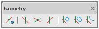
It contains:
-
The button to enable the isometric drawing mode;
-
Three buttons to set isometric planes (ISODRAFT1, ISODRAFT2 and ISODRAFT3 commands or an option on ISODRAFT command);
-
Buttons to create isorectangles, isocircles and isoarcs (rectangles, circles and arcs in an isometric projection).
Isometric drafting mode
For isometric drawing, use the Isometric drafting mode. The mode is enabled by entering the ISODRAFT command, by
 button on the Isometry toolbar or by
  button in the status bar.

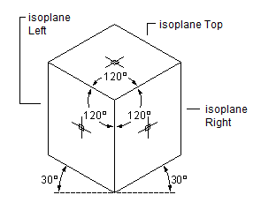
The isometry mode allows for quick switch between three isometric planes (isoplanes) by F5 key or by clicking an appropriate button on the Isometry bar.
-
 Isoplane Left. The plane allows you to create objects oriented along the axes of 90 and 150 degrees.
-
 Isoplane Right. The plane allows you to create objects oriented along axes of 30 and 90 degrees.
-
 Isoplane Top. The plane allows you to create objects oriented along the axes of 30 and 150 degrees.
Isometric Mode’s Impact on Drawing Settings
When you enable isometric drafting mode, nanoCAD automatically changes the following settings to match the selected isoplane:
-
Orthogonal direction
-
Snap orientation
-
Grid orientation
-
Polar tracking angles
-
Orientation of isometric circles, arcs, and rectangles as they are created
Creating Isometric Objects
The following commands are used to create circles, arcs, rectangles in the current isometric plane:
-
To create a circle in the current plane, use
 ISOCIRCLE command that starts the ELLIPSE command with the Isocircle option;
-
To create a rectangle in the current plane, use
 ISORECTANGLE command that starts the RECTANGLE command with the Isorectangle option;
-
To create an elliptical arc in the current isometric plane, use
 ISOARC command that starts creating an elliptical arc by the ELLIPSE with the Arc > Isoarc option.
Related System Variables
The SNAPSTYL system variable allows you to change the drawing mode. The variable values are integers.The SNAPISOPAIR system variable allows you to change the current isometric plane in the current viewport. The variable values are integers.
.png)
.png)
The basic tools (Sheet solid, Bend edge, Bend over segment, and Fold by sketch) create standard parts from sheet metal. Folds can be bent and unbent at any time, and corners are handled by a variety of reliefs and bends.
For specific sheet metal parts, there are the Shell and Ruled shell tools, plus additional tools quickly add commonly used sheet metal elements, such as these ones:
-
Collars
-
Holes
-
Plates
-
Shutters
-
Stamps
-
Stiffeners
-
Undercuts
The Unbend tool makes flat drawings of 3D sheet metal parts.
.png)
Mechanica has transitioned to a new materials database management system that takes into account user wis list items. The new database includes elements from the general database of objects, as well as these improvements over the old one:
-
More complex and varied materials
-
Custom materials
-
Multi-line notes for materials
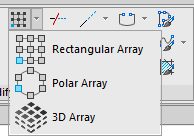
The commands now work interactively, without needing a dialog box.
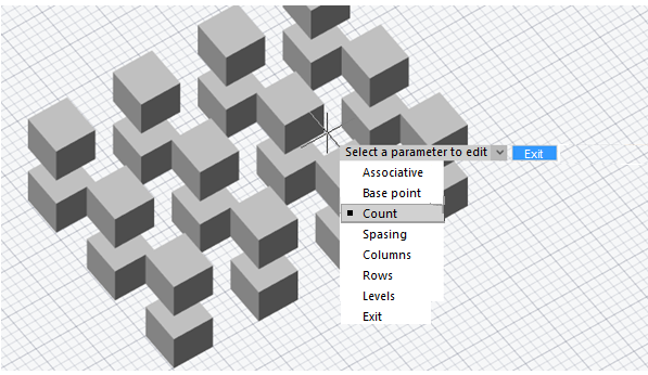
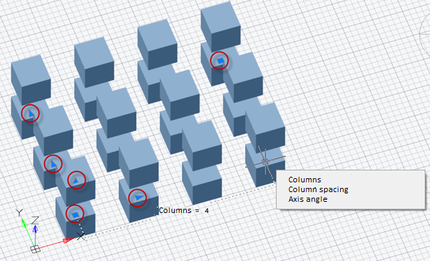
As well, nanoCAD now creates associative arrays. The objects that make up an associative array are stored as a single array object. The Array - Associativity system variable toggles arrays between associative and non-associative. Associative arrays allow you to change the number of objects and the distances between them through grips on the array or with the Properties panel.
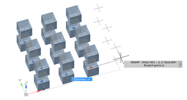
Each release of nanoCAD adds new commands. To make it easier to focus on the design at hand, the primary 3D modeling commands are now grouped by mode in the Modeling Modes section of the 3D Tools ribbon:
-
Parametric
-
Direct
-
Sheet
-
Meshes
When users switch between modeling types, the ribbon automatically changes the commands displayed to those specific to the selected modeling mode. For example, when a user selects Parametric modeling mode, the ribbon changes to show commands for creating 3D geometry based on parametric sketches.
.png)
.png)
.png)
When the user selects Meshes modeling mode, the commands standard for creating 3D surfaces become available.
.png)
Commands that apply to all types of modeling such as, for example: Chamfers and Rounds, Boolean operations, commands of construction geometry, manipulation and others are always visible to a user.
Mechanica’s Hole fill tool improves the conversion to threaded holes:
-
Hole diameters becomes the outer diameter of the threads
-
Internal thread diameters depend on the snap selection
-
Names of metric threads are set
The Tables of holes tool now constructs the left coordinate system of holes.
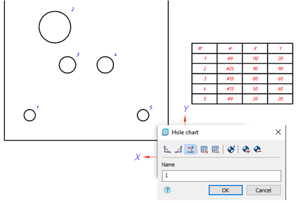
- add remove and modify block objects while maintaining the integrity of dynamic block parameters. Actions concern objects that are not involved in the block parameterization;
- convert any block to dynamic;
- replace the insertion point.
New Block Base Point Relocation
The base point of blocks can be relocated with the BBASEPT command. The base point locates the insertion point of blocks, and the position of the grip.
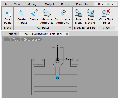
Reset block
Editing dynamic block inserts and then re-editing this block definition may distort the appearance of its inserts. The Reset block (RESETBLOCK) command resets the parameters of the selected dynamic block inserts to default values. It is opened from the context menu of the selected inserts or from the command line.
.png)
New report generation options are added to the interior composition list:
-
Areas of premises with the same cladding can now be summed or kept separate
-
Premise numbers and names can now be placed in separate columns
-
Dimensioning in UCSes is corrected.
-
Symbols for surfaces are corrected.
Now there is a possibility to transfer and save user interface configuration. To transfer settings between versions or from one computer to another, use two commands: Import UI (UIIMPORT) and Export UI (UIEXPORT).
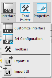
The Export UI command allows you to save a package of individual configuration, while the Import UI command applies it to the current version of the program.
Export UI allows you to save both the composition of interface elements (ribbon, toolbars, etc.), configured in the Customize user interface dialogue box, and the display with location of interface elements (location of toolbars, palettes, command line, visual style of interface, way of the ribbon display, size and location of the program window).
Thus, you can quickly and easily transfer user configurations for convenient work with the program, as well as save the configurations package to prevent them from being lost.
If necessary, you can also edit LSP-file, which describes Import UI and Export UI, commands and edit the list of file formats included in the configuration package being exported.
.png)
The 3D-tangency constraint joins surface tangents that are more complex than what the existing 3D-merge constraint can handle. It creates tangents between, for example, the following objects:
-
Cylinders to planes or cylinders
-
Cones to planes
-
Spheres to cylinders or planes
-
Circular edges to straight or circular edges
3D-tangency constraint:
.png)
3D-symmetry constraint:
.png)
Redesigned Field Dialog Box
The FIELD command’s dialog box is redesigned:
.png)
Additional format dialogue
More detailed formatting of numeric values is now available in the field editor. The Additional format button opens the dialogue box, where you can set the conversion factor, zero suppression, additional text, numeric separator.
.png)
Option for fields inside a block
Display value for block reference – the checkbox is displayed only for object properties fields that are located inside the block. For example, when editing a field inside a block attribute definition.
.png)
.png)
The parameter obliges the property to calculate its value relative to the size and orientation of the block reference in the drawing, and not relative to the internal block description space. So, for example, the coordinates of the center of the object included in the block will be calculated relative to the drawing coordinate system, and not relative to the coordinates of the block definition.
Commands to Work with Groups
Commands for working with groups now have their own place on the ribbon (Group section of the Main tab) and Group toolbar. This makes it more convenient to carry out grouping and ungrouping outside of the Object Grouping dialog box, and allows you to create unnamed groups.
.png)
.png)
.png)
|
New group (GROUP) |
A new command to create a group of objects. Unlike the New option, the GROUP command allows you to create both name and unnamed group. |
.png)
|
Exploding a group (UNGROUP) |
Exploding a group or ungrouping. |
.png)
|
Editing a group (GROUPEDIT) |
Adding or deleting objects from a group. |
.png)
|
Dialogue for creating groups (CLASSICGROUP) |
Displays the Object grouping dialogue box to manage groups. In the previous program versions this dialogue box was called by the Group command (GROUP). |
nanoCAD offers a new way to recover drawings accidently lost when exiting drawings without saving, such as when closing all open drawings at once. In other cases, objects are erased from drawings, and then the drawings are saved and closed, after which the undo/redo mechanism no longer works.
The new rescue mechanism restores them from a temporary storage, and is enabled in the Options dialogue box: Save documents section > File History.
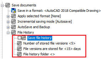
-
Save file history (FILEHISTORY variable) – determines whether the auto-save history is enabled (0 – disabled or 1 – enabled)
-
Number of stored file versions (FILEHISTORYMAX variable) – determines the maximum number of auto-saved version of each drawing file, up to 32767 versions.
-
File versions are stored for <15> days (FILEHISTORYDURATION variable) – determines the duration to store each auto-saved file, up to 32767 days (approximately 90 years).
-
File history folder – specifies the folder in which to store auto-saved files
The Open file history command (OPENHISTORY) opens files from the archive storage.
The earliest files are deleted from storage automatically once the number of archive files specified by FILEHISTORYMAX is reached. When closing nanoCAD, the storage period for files in the archive is checked, and files with a life of longer than FILEHISTORYDURATION are deleted automatically.
-
Vector maps from OpenStreetMap
-
Raster maps from ArcGis, Microsoft Bing, Google Maps, MapBox, OpenStreetMaps, OSM Topo, and Yandex Maps
-
For some providers, additions map types are supported, such as streets, satellite, hybrid, relief, and topographic
.png)
Three-dimensional terrain models can also be placed as overlays.
.png)
.png)
Improved Import and Export
- Added import and export of clouds files in E57 and ReCAP (*.rcs) formats
- Improved algorithm for importing cropped volumes
- Drag and drop nanoCAD point cloud files (*.npc) into drawings
- Set drawing measurement units in the Import dialog box
- Export point clouds in 3D PDF format
New Commands for Clipping Clouds
- Added commands for clipping cloud by sphere and cylinder shapes
- Improved clipping command interface
- New command to invert point cloud clipping boundaries
3D Geometric Snaps
The following three-dimensional snaps recognize geometry in point clouds. They are turned on and off through the Drafting Settings dialog box or at the status bar:- Point Cloud Edge Node
- Point Cloud Edge Nearest
- Point Cloud Edge Perpendicular
- Point Cloud Plane Nearest
- Point Cloud Plane Perpendicular
- Point Cloud Feature Surface
- Point Cloud Feature Axe Node
- Point Cloud Feature Axe
- Point Cloud Feature Center
.png)
.png)
<path>/ncad.exe [<path>/drawing_file] [-list "sheet name"]The named view saved in a drawing is displayed upon opening the drawing with the new -v switch:
<path>/ncad.exe [<path>/drawing_file] [-v "view name"]Either the - or the / character can be used for the switch.
Copy OLE-link Command
The new Copy OLE-link (COPYLINK) command copies the current view to the clipboard so that it can be linked in other OLE-aware applications. An object of nanoCAD drawing type is created in the other program. This means you can insert nanoCAD drawings into Word documents as OLE objects, which can then be edited in nanoCAD by just a double-click.
.png)
Renamed OLE Commands
The names of OLE- related commands are changed to be more intuitive in the toolbar/menu interface:
In the Insert menu, the Object… item becomes OLE-Object…. (The ellipsis indicates a dialog box will be opened.)
In the Edit menu, the following items are renamed:
-
Copy view becomes Copy OLE-link
-
Links… becomes OLE-links…
-
Update all links becomes Update all OLE-links
OLE in the Properties Panel
Properties are added to the Properties panel for OLE objects.
- While holding down the Alt key, and then select any point on the locator circle
- Choosing one of the four marked points to rotate a view by 90◦.
The arrow points to the new view rotation position.
.png)
.png)
Arc Direction by Cursor Movement
nanoCAD now draws arcs (including elliptical ones) in the direction that the cursor moves. This applies to the following arc construction methods:
-
Center-Start-End
-
Start-Center-End
-
Elliptical arcs
You can also change the direction for constructing arcs by holding down the Ctrl key.
Circle by Three Tangents
Circles can now be drawn tangent to three other objects (menu Draw > Circle).
.png)
.png)
Circles Tangent to Splines and Ellipses
Now the command to create a circle by tangent, tangent and radius, allows you to specify splines, ellipses and elliptical arcs as tangents. As well, creating circles tangent to arcs or other circles is improved.
.png)
Breaking Ellipses and Closed Polylines by Two Points
When breaking an ellipse or a closed polyline with two points, the sequence of picking points determines which part of the objects to remove. (Previously, the same part always remained, regardless of the pick order.)
Lengthening in Both Directions
Lengthen (LENGTHEN) command now lengthens open objects symmetrically in both directions, through a new switch Two sides/One side. This is useful, for instance, for increasing the lengths of centerlines in both directions.
Editing Spline Fit Points with Ctrl
Spline fit points can now be edited by holding down the Ctrl key while clicking on a grip, just as with polylines. The context menu is updated to reflect this.
.png)
New Lasso Object Selection
Objects can now be selected using the lasso method: while holding down the left mouse button, move the cursor around objects. Objects are selected by a lasso or a rectangular selection frame, depending on your actions:
-
Move the cursor in the drawing area while holding down the left mouse button, the lasso outline is drawn. To end the selection, release the mouse button.
-
A single click in an empty area of the drawing starts a rectangular selection window. To complete the selection, click a second point.
The direction of cursor movement determines which objects are selected:
-
Move the cursor to the right, and objects entirely inside the area are selected. The selection area (window or lasso) is shown with a blue semi-transparent fill.
-
Move the cursor to the left, and objects inside and crossing the boundary are selected. The selection area (window or lasso) is shown with a green semi-transparent fill.
While selecting objects by the lasso method, you can cycle through three lasso modes by pressing the Space key:
-
Select only objects completely inside the lasso area
-
Select all objects inside and crossing the lasso
-
Select only objects crossing the lasso line
.png)
.png)
.png)
.png)
.png)
.png)
Selection Preview Filter
Three more objects types are added to the Selection Preview Filter dialog box: Group, Mesh, and Polyface Mesh.
.png)
Interactive Actions with the Right Mouse Button
When you drag-and-drop objects while holding down the right mouse button, a shortcut menu appears with additional actions: Move here, Copy here, Paste as block. Select one to perform the action.
.png)
Multiple Copies with Ctrl
While moving, rotating, scaling, or mirroring objects with grips, hold down the Ctrl key to create copies:
-
Select one or more objects
-
Click on a grip
-
Press the Spacebar to switch between copy, rotate, scale, or mirror actions
-
Hold down Ctrl, and then click to locate copies of the selected objects
.png)
Enhanced Rotate Command
The ROTATE command gains the Key point option. It combines the base point with the reference angle. When you specify a reference angle, the first point you pick for the angle is the base point, about which rotation takes place.
Isolation/Unisolate History
.png)
.png)
.png)
Grouping Undo/Redo
The new BEgin and End options in the Undo and Redo commands (UNDO, REDO) combine a sequence of actions to be reversed in a single step. Those commands performed after setting BEgin and before setting the End option are undone simultaneously. You can create multiple BEgin and End sets, each of which are reversed in sequence.
1. After setting the BEgin option, the Begin of command group item appears in the command list.
.png)
2. Following this, any commands you execute are added in the undo list of operations, one by one.
.png)
4. Once the End option is applied, all actions in the undo list between the beginning and the end collapse into a single group of undoable commands.
.png)
5. At this point, these commands can only be reversed together.
MATCHPROP Undo
When previously you copied properties to large numbers of objects with the MATCHPROP command, you may have accidentally copied them to a wrong object. In this case, you had to cancel the command and start copying properties anew.
To avoid this problem, a local undo option is added to the MATCHPROP command. The option appears when you specify the Select destination object(s) prompt.
.png)
.png)
Polar Spacing
The new Polar Spacing option specifies the spacing distance during polar snap, if the Polar snap (POLARDIST system variable) is turned on. When Polar Distance is set to zero, the polar spacing is equal to the Snap X spacing. Polar spacing is effective works when polar or object tracking modes are enabled.New Snap Types
-
Grid snap – sets the snap as a rectangular grid with spacing specified by Grid Spacing
- Rectangular Snap – sets rectangular as the snap style and deactivate isometric drawing mode
- Isometric Snap – sets isometric as the snap style and activates the isometric drawing mode
- Polar – sets the snap as a polar array. With polar snap and polar tracking enabled, the cursor snaps to tracking lines from the base point at angles specified on the Polar Tracking tab.
-
Turn on Grid snap
-
Set the grid to isometric snap
-
Switch to Polar snap
.png)
Polar spacing
Manages the spacing distance of the polar snap.
Spacing – polar snap spacing. Becomes available, if the Polar snap (POLARDIST system variable) is set. In case of zero value, the polar spacing is equal to the snap spacing interval by X. Works when polar or object tracking mode is enabled.Follow Dynamic UCS
The new Follow dynamic UCS setting orients the grid plane to match the XY plane of dynamic UCS automatically (GRIDDISPLAY system variable).Now you can set object snaps temporarily. To do this, enter a snap keyword during a command when you are prompted for a point, and then press Enter. The snap is set temporarily.
.png)
.png)
.png)
The full list of object snap keywords is available by typing OS_ at the command prompt, or from the status bar.
.png)
The list of object snap keywords is given by the table:
|
Keyword |
Snap type |
|
TT |
Tracking point |
|
FROM |
From |
|
M2P |
Mid between two points |
|
END |
Endpoint |
|
MID |
Middle |
|
INT |
Intersect |
|
APP |
Apparent intersection |
|
EXT |
Line extension |
|
CEN |
Center |
|
QUAD |
Quadrant |
|
TAN |
Tangent |
|
PERP |
Perpendicular |
|
PAR |
Parallel |
|
INS |
Insertion point |
|
NODE |
Node |
|
NEAR |
Nearest |
|
NONE |
Disabling object snap |
A new option Replace Z Value with Current Elevation works with for object snaps in 3D space. When enabled, it snaps to points on the XY plane in the current UCS.
The figure below shows two 3D polylines drawn object-snapped to the vertices of a mesh. The polyline in red uses the normal object snap modes; the one in blue with the Z-coordinate replacement option enabled.
.png)
.png)
In this mode, the Z coordinate value is replaced with one of the following:
-
The value of its projection to XY plane
-
The value of its projection to a plane parallel to the XY plane at the level specified by the ELEVATION variable, if it is non-zero).
Change the value of the ELEVATION variable to have the points snap at a specific distance above (positive values) or below (negative values) the XY plane.
The option is enabled in the Snap settings section of the Options dialog box, and is synchronized with the OSNAPZ variable.
.png)
.png)
.png)
Support is added for the DYNDIVIS variable when editing objects by grips;
Not all dynamic dimensions can be seen on the screen simultaneously. The number of simultaneously displayed dimensions is controlled by the DYNDIVIS variable. Depending on its value, the following can be displayed simultaneously:
-
Only one dimension (DYNDIVIS = 0)
.png)
-
Only two dimensions (= 1)
.png)
-
or all dimensions (= 2)
.png)
If only one or two dimensions are displayed simultaneously, and you need to display others, this can be done by cyclically pressing the Tab key. Press Tab until the desired dimensions are visible. On subsequent cursor movement, the selected dimensions will continue to be displayed.
.png)
.png)
.png)
Dynamic input is enhanced through the following additions:
-
Input length and angle increment fields appear when editing objects with grips
-
Dynamic input implemented for ellipse creation
-
Dynamic input fields appear for the second and the next points when drawing a variety of objects in UCS
-
Input and editing of dynamic dimensions for 3D polylines in UCS
-
DYNDIVIS variable added for editing objects with grips
-
Bugs while using dynamic input while constructing lines and circles are corrected
Using hyphen in bulleted lists
Now you can create bulleted lists using dashes.
.png)
Aligning the last line
When you add a Tab to the end of the last line of distributed multiline text, then it is aligned to the left and remains so after editing is completed.
Blocking subdimensional text
Now the cleared Dimensions box in the Main options tab of the Design Settings dialogue box (Section Edit > by double-click) also blocks editing by double-click and subdimensional multiline text.
.png)
Hiding the text background for different type objects
To hide background for multiline text, multiline attributes and multileader multiline text use a separate command .png) on the ribbon.
on the ribbon.
.png)
Objects can be selected before or after the command is performed. This allows you to apply the command to several selected different type of objects.
The command displays the Background mask dialogue box, which will display parameters for hiding background for multiline text in the first selected object.
.png)
When switching the text type of the Default value from multiline text to single-line text in the Attribute definition dialog box (ATTDEF command), a warning is now issued when the text is so long that it would be truncated. Previously, the text was completely erased.
.png)
When switching from a single-line attribute to a multiline one, the text is also preserved.
The following bugs in multileaders are corrected:
-
If a TTF font was used, then spaces were not underlined
-
Text was incorrectly underlined in multileaders with Bottom or Top attachment and Underline and Middle justification
-
Text in multileaders with Top attachment had its Left alignment changed to Right
The Modify > Multileader menu gains multileader editing commands:
.png)
For dimensions and multileaders created in other CAD systems, associativity with objects is maintained when they are imported into nanoCAD.
The associative links of dimensions with objects can be broken by shifting the grips of extension lines.
The Break dimension command (DIMBREAK) is renamed MDIMBREAK.
The Restore dimension command (DIMUNBREAK) is renamed MDIMUNBREAK.
A new version of the Break and restore dimension command (DIMBREAK) combines the functions of both commands.
Sheet lists can now be generated from sheet set as a table. From the Sheet Set toolbar, select the name of a sheet set and sheet group, then from the context menu select the Insert Sheet list item.
Templates provided for sheet sets contain the required settings. To change the style of the sheet list, edit the table style with the table style dialog box (TABLESTYLE command).
.png)
As well, you can directly select a different page setup for each sheet from the drop-down list of the Page setup option.
.png)
.png)
.png)
.png) Viewport align (ALIGNSPACE) command adjusts the pan and zoom factor of objects in layout viewports based on an alignment point in model and paper space. Points specified in model space are aligned to the points set in paper space.
Viewport align (ALIGNSPACE) command adjusts the pan and zoom factor of objects in layout viewports based on an alignment point in model and paper space. Points specified in model space are aligned to the points set in paper space.
.png)
-
Specifying a point in model space and another point in paper space offsets (pans) the view
-
Specifying two points in model space and two in paper space sets zoom scaling, panning, and rotation. The zoom factor and UCS rotation are adjusted according to the points specified.
.png)
Now when importing PDF files using the Import PDF (PDFIMPORT) command, text data are placed on the same layers, on which they were when creating a PDF file. Names of layers will start with PDF prefix. For this, in the Import PDF dialogue box, when selecting layers parameters, select the Use PDF layers option;
Solid fills in nanoCAD Platform are now imported by a fill, and not as a contour as before;
A bug with importing gradient fills from PDF, when some types of gradient fills were not imported into the drawing has been fixed. Gradient fills are imported as raster images.
.png)
.png)
You can optimize the work in the program when connecting to a workstation remotely via RDP by using the enhanced DirectX compatibility mode in the Options dialogue.
.png)
If the box is checked, DirectX 9 is used. When cleared, the default DirectX version is used. In most cases it is DirectX 11, but if it is not supported by the system, then it is DirectX 9. You can also switch DirectX version by the NCGS_TOGGLE_DIRECTX command.
nanoCAD now continues to work for another hour following the loss of your license. This allows you to complete your work. You will be reminded periodically that your license has expired.